
Boosted Pierce

The Pierce oscillator configuration is notable for its simplicity and effectiveness in generating RF signals for Morse code transmission. The aperiodic nature of the oscillator allows for stable operation without the need for complex tuning mechanisms, making it particularly suitable for amateur radio applications. The choice of using a triode and a screen-grid tube enables better control over the output characteristics, facilitating improved signal integrity and modulation capabilities.
The design's flexibility is evident in the various configurations and adaptations that can be employed, allowing operators to customize the circuit based on their specific needs and available components. The use of a voltage divider for screen voltage regulation is a key feature that enhances performance by providing stable operating conditions for the final amplifier stage.
Furthermore, the ability of the circuit to maintain functionality even when the oscillator tube is removed highlights the robustness of the design. This characteristic can be particularly advantageous in field conditions where component reliability is critical. However, caution must be exercised to prevent excessive excitation of the crystal, which may lead to damage.
In summary, the Boosted Pierce oscillator presents a practical solution for multiband Morse code transmission, combining ease of use with effective performance. Its historical significance and ongoing popularity among amateur radio enthusiasts underscore its enduring legacy in the field of RF circuit design.a Pierce "aperiodic" oscillator driving a non-neutralized power amplifier for a multiband Morse code transmitter that requires just one coil and minimum adjustment. And then one day you happen to unplug the oscillator tube only to find that it still works! This page explores that topology, the Boosted Pierc e (Figure 1), from its Great Depression beginnings through its canonization as a ubiquitous "glowbug" design that just won`t go away. Fundamental to understanding the circuit is that it`s an aperiodic-anode tri-tet oscillator that uses separate triode and screen-grid (tetrode or pentode) tubes.
Figure 1 ” Boosted Pierce transmitter based on the version described by Don Mix, W1TS, in October 1968 CE QST. Some variations use more or less voltage, regulated or not, on the oscillator; some variations include a cathode bias resistor in the final amplifier and some don`t; some key both stages and some key only the final amplifier; this version uses a voltage divider to supply final screen voltage rather than the series resistor used in many versions.
All have the same aim: better performance than an oscillator-only transmitter without the fuss and bother of neutralization ”but it turns out that neutralization is well worthwhile for multiple reasons. Test point T allows measurement of the final grid current, with every 0. 1 V across the associated 100-ohm resistor equating to 1 mA of grid current in the 5763 ”a value worth measuring, because underdrive is likely at 7 MHz and higher frequencies in every Boosted Pierce design that does not overstress its crystal.
RS1 and RS2 are proportioned to set the screen voltage to 204 V, key down, in my test version. (Schematic symbols [Tubepad] and original Mix "Novice Special" Boosted Pierce transmitter schematic by Gary Johanson, WD4NKA) Figure 2 ” Why the Boosted Pierce can produce output with its oscillator tube removed or disabled: The crystal is connected between the amplifier grid and ground through the oscillator`s grid feedback capacitance (in this case, 50 pF) and (if the oscillator tube is disabled but left in its socket and its cathode is bypassed to common for RF, as it is here) the oscillator tube`s grid-to-cathode capacitance (around 10 pF). . excessive excitation will fracture a quartz crystal rendering it useless. The following are the outstanding sources of excessive excitation:. (11) in certain instances, by removing the plate voltage from a Pierce Oscillator employing an untuned tank.
This is a unique situation in that the buffer stage, which follows the oscillator, can act as a crystal controlled oscillator. The crystal is effectively connected between the control grid and ground of the buffer tube and, if the buffer plate tank is tuned to the crystal, that stage can act as a crystal oscillator when the voltage is removed from the oscillator stage proper.
If conditions in the buffer stage are incorrect for a crystal oscillator, the crystal may be fractured. In "Airline Transmitter Adaptable for Amateur Use" (Radio, November 1937 CE, pages 32 38 and 81), G. E. Smith, W4AEO, described a commercial transmitter design based on a 42 pentode Pierce oscillator: This oscillator, with crystal between control grid and plate, is commonly called the Pierce Circuit.
If a coil-condenser tank is substituted in place of the crystal, it will be seen at once that it becomes similar to an ultra-audion or Colpitts circuit. This circuit was selected after all types of crystal oscillators had been tested, complete sets of readings had been tabulated, and the advantages and disadvantages of each taken into consideration.
Each type of oscillator was keyed by various methods and the shape of the keying was checked on the oscilloscope. The only disadvantage of the Pierce oscillator is low output as compared with the more common oscillators, pentode, tri-tet, 6L6, et.
But a crystal oscillator sho 🔗 External reference
Related Circuits
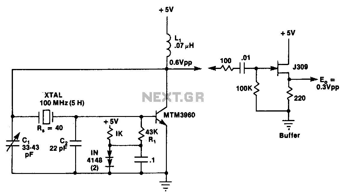
This circuit is a conventional Pierce type oscillator that utilizes a JFET. It employs fundamental mode crystals and demonstrates good performance and reliability when a low noise JFET is used. The feedback is regulated by the capacitance C1, which...
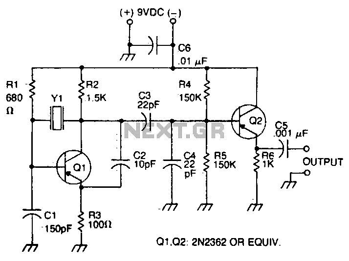
The oscillator transistor is Q1, and the crystal is placed between the collector and base. Feedback is improved by the use of the collector-emitter capacitor C2. Transistor Q2 is used as an output buffer. The circuit described features an oscillator...
The JFET Pierce oscillator is stable and simple. It can serve as the clock for a microprocessor, a digital timepiece, or a calculator. With a probe at the output, it can be utilized as a precise injection oscillator for...
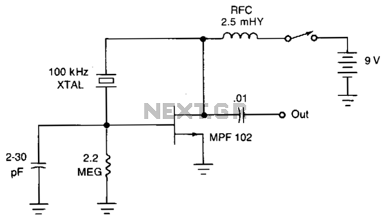
The JFET Pierce oscillator is stable and straightforward. It can serve as the clock for a microprocessor, a digital timepiece, or a calculator. With a probe connected to the output, it can function as a precise injection oscillator for...
The current meter has a measurement range from 100 pA to 3 mA full scale. The voltage across the input is 100 µV at the lower ranges, increasing to 3 mV at 3 mA. Buffers on the operational amplifier...
This circuit is a conventional Pierce-type oscillator that utilizes a JFET. It operates with fundamental mode crystals, offering decent performance and reliability when a low noise JFET is employed. The feedback is regulated by the capacitance of C1 from...