
Super Buffer for Guitars
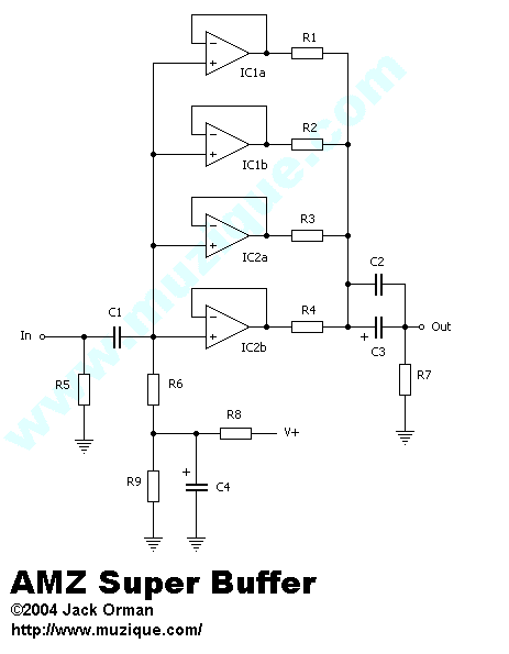
The design of the buffer circuit is straightforward yet effective, utilizing four opamps in parallel to achieve a robust output drive. Each opamp's output is coupled through individual resistors R1 to R4, which not only ensure load sharing but also provide isolation to prevent loading effects that could degrade performance. The use of resistors R5 and R6 plays a critical role in defining the input impedance characteristics of the circuit. The choice of capacitors C2 and C3 is strategic, allowing for both low-frequency coupling and maintaining high-frequency integrity, which is essential for preserving the quality of the audio signal across varying loads.
In terms of implementation, the use of dual opamps allows for flexibility in component choice, enabling experimentation with different opamp models to achieve desired tonal characteristics. The circuit's adaptability to various opamps also means that users can optimize performance based on personal preferences or specific application needs. Furthermore, the ability to operate with a single opamp not only conserves power but also simplifies the circuit for less demanding applications.
Overall, this buffer circuit serves as a versatile solution for signal integrity in pedalboard setups, ensuring that long cable runs do not compromise audio quality while providing the necessary drive for diverse audio equipment. Its design principles can be applied to various audio applications beyond guitar setups, making it a valuable addition to any electronic engineer's toolkit.There are situations in which very long cable runs are necessary from the pedalboard to the amplifier, or a more powerful driving circuit is needed to the heavy load presented by devices in parallel. A good buffer box is the solution. The best buffer board will present a high impedance to the input while having a low impedance output.
This insures that the maximum clear signal will pass through unchanged to the output, and a low impedance drive can send the signal through long cables without losing much strength or response. There are numerous special purpose chips that are designed as buffers for driving very long lines and/or capacitance loads.
These ICs can be difficult to find and expensive. A simple solution for stompbox purposes is to parallel opamps and thereby boost the output drive. With attention to a few details, this is a simple project to build. The circuit has four opamps placed in parallel. The outputs are isolated by resistors R1 through R4 which make sure the opamps share the output drive and no single one is carrying the bulk of the load. Resistor R5 is an pop prevention component and can be eliminated if desired. The value of R6 is essentially the input impedance if R5 is not used. When R5 is included, the input impedance is the parallel value of R5 and R6. Two capacitors are used on the output - since we do not know what load this circuit may be driving and we want to get full response, a 10uF output capacitor (C3) is a good value to chose.
A 0. 1uF metal film (C2) is placed in parallel with C3 to insure that the response remains flat at high frequencies where the rising impedance of electrolytics could effect the sound. C2 could be left out without sacrificing much. An additional tweak is to make the R6 resistor a metal film component for lower noise. If you are making this mod, you might as well make R5 and R7 metal film also since they are all the same value.
The circuit could be made with a quad opamp package but it is more interesting to use a pair of dual opamps. While the circuit is designed to use two identical dual opamps, there is no reason that one cannot make substitutions to check out the sound.
For instance, put an NE5532 in the IC1 socket and an RC4558 in for IC2. Is there are difference in the sound Feel free to experiment! Also, the circuit works well with only one IC chip in place. It can be used in this manner to reduce power consumption requirements. To reduce current requirements even more, use FET opamps like the TL072 or similar. If you want to disable all but one of the buffers, remove IC2 from its socket and also remove R2 (100 ohms). This will provide only a single opamp output drive via IC1a for use as a basic buffered output but it is more fun to be able to mix and match opamps for subtle variations of tone.
The best place for the Super Buffer is at the end of your chain of pedals. In this position the buffer will be a line driver for the long cord back to your amp or mixer. Alternately, it can be at the front of the pedal chain which is good if you have all true bypass pedals. No matter where you place it, the AMZ Super Buffer can clean up your sound and allow the maximum tone from your pickups to shine through!
If the 5532 or OPA2604 opamps are used, there is enough drive from this circuit to power a set of headphones! Of course, it is not optimized for that purpose and the flat frequency will not sound good, but the power is there.
🔗 External reference
Related Circuits
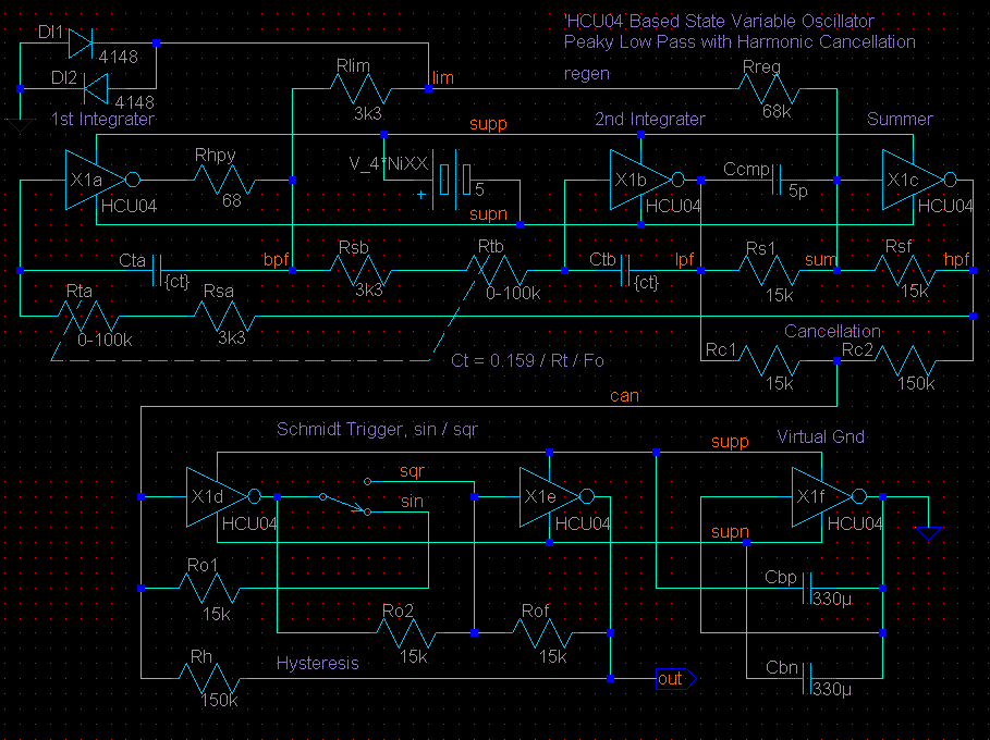
This circuit is based on the State Variable Band Pass Filter, incorporating amplitude-limited regenerative feedback. The State Variable Band Pass Filter (SVBPF) is a versatile filter design that allows for simultaneous control over the center frequency, bandwidth, and gain. This...
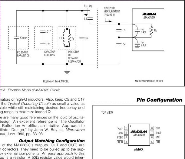
The MAX2620 integrates a low-noise oscillator with two output buffers in a cost-effective, plastic surface-mount, ultra-small uMAX package. This device combines functions that are typically achieved with discrete components. The MAX2620 is designed for applications requiring precise frequency generation with...
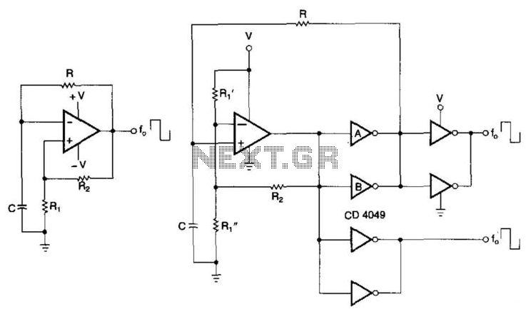
CMOS buffers added to an operational amplifier oscillator enhance performance, primarily due to the asymmetry and variability of the operational amplifier's output saturation voltages. The integration of CMOS buffers into an operational amplifier (op amp) oscillator circuit serves to significantly...
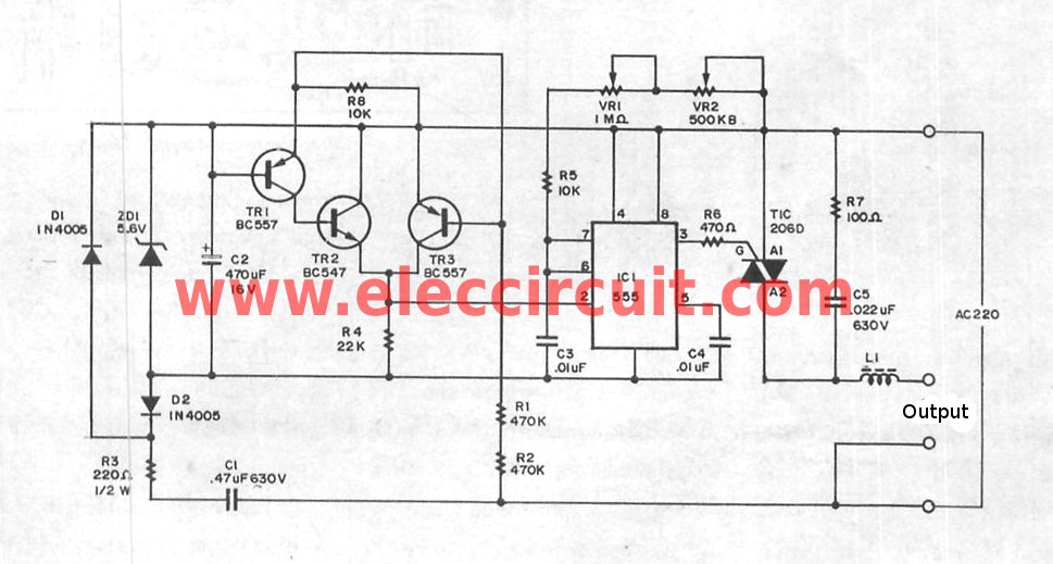
The super dimmer is an improved version compared to the standard dimmer currently in use. Testing its performance will provide a clearer understanding of its advantages. The super dimmer operates using advanced technology that allows for finer control over...
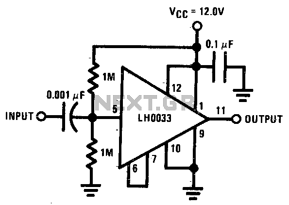
The input is DC biased to the mid-operating point and is AC coupled. Its input impedance is approximately 500K ohms at low frequencies. For DC loads referenced to ground, the quiescent current is increased by the load current set...
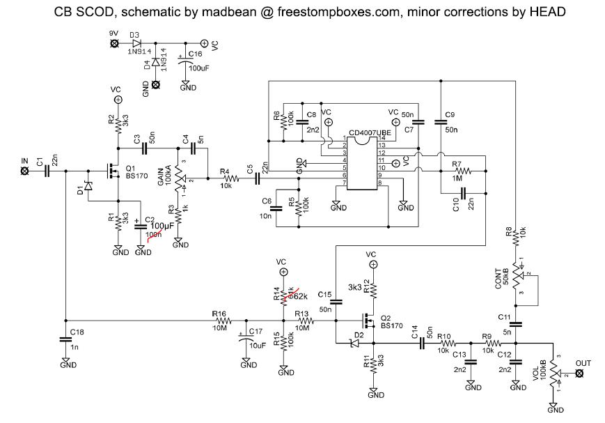
The Super Charged Overdrive has been part of the Catalinbread range for some time and has undergone three style makeovers. It is a high-gain pedal that utilizes old logic chips with internal MOSFETs for its gain structure and clipping....