
Single supply AC buffer amplifier
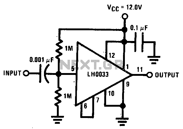
This circuit employs DC biasing to establish a stable operating point, ensuring optimal performance and linearity in signal amplification. The AC coupling indicates that the circuit is designed to block any DC component of the input signal, allowing only the AC variations to pass through. This configuration is particularly useful in audio and RF applications where it is essential to prevent DC offsets from affecting downstream circuitry.
The specified input impedance of approximately 500K ohms at low frequencies suggests that the circuit is designed to minimize loading effects on the previous stage, allowing for maximum signal transfer. High input impedance is crucial in applications where the source impedance is also high, as it prevents signal degradation.
The mention of DC loads referenced to ground indicates that the circuit can accommodate various load configurations while maintaining a stable quiescent current. The quiescent current, which is the current flowing through the circuit when no input signal is present, is adjusted based on the load current dictated by the input DC bias voltage. This characteristic is significant in ensuring that the circuit remains within its linear operating region, thereby enhancing the overall performance and reliability of the system.
In summary, this circuit design effectively balances DC and AC components, providing flexibility in load conditions while maintaining high input impedance and stable quiescent current, which are essential for high-fidelity signal processing.The input is dc biased to mid-operating point and is ac coupled. Its input impedance is 11 - OUTPUT approximately 500K at low frequencies For dc loads referenced to ground, the quiescent current is increased by the load current set at the input dc bias voltage. 🔗 External reference
Related Circuits
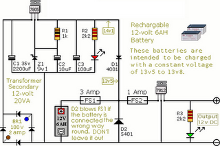
The following circuit illustrates an Alarm Power Supply Circuit Diagram. Features include a 1-amp current output, suitable for a Modular Burglar Alarm operating at 12 volts. The Alarm Power Supply Circuit is designed to provide a stable and reliable power...
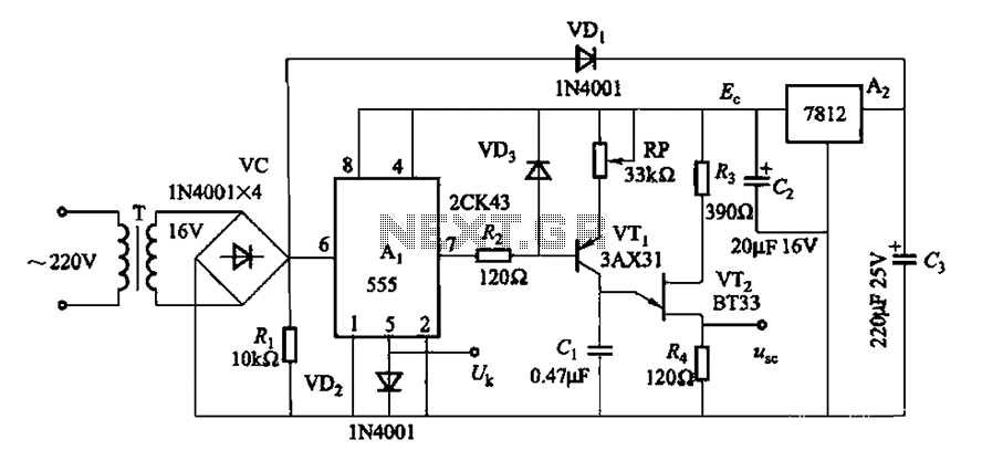
Both circuits can synchronize trapezoidal wave voltage, which is converted into intermittent small rectangular pulses. Its working principle involves periodic operation in synchronization with the grid frequency of the zero-volt switching voltage of the DC chopper. Due to the...
The circuit is based on a simple inductor-capacitor filter circuit, and needs only a pot and a small light bulb to set and stabilise the oscillation. The frequency is fixed, and with a good inductor should be capable of...
The circuit was designed to create a line preamplifier using double triode tubes. It consists of three parts, including the main preamplifier. The line preamplifier circuit utilizing double triode tubes is structured to enhance audio signals by amplifying low-level signals...
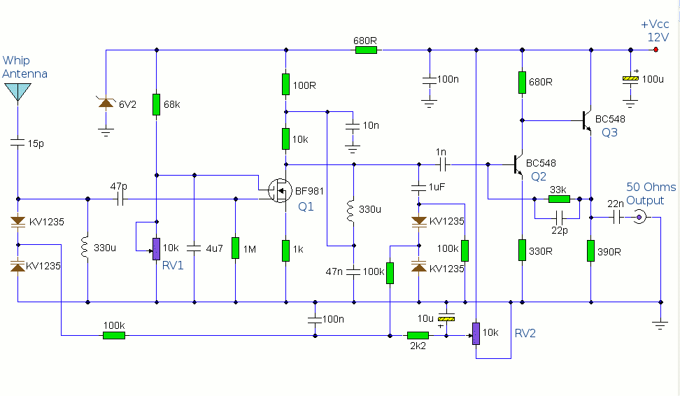
The antenna amplifier circuit comprises approximately 40 components, featuring two NPN transistors (BC548), one MOSFET (BF981), two varicap diodes (KV1235), and a 6.2V zener diode. It includes a 330µH inductor/coil, which can be modified for operation on different frequency...
This simple and slightly unconventional circuit provides a clear indication of the supply voltage level in a larger device. When the indicator receives a stable 12 volts at its input, LED1 emits a steady yellow light that appears continuous...