
Super Fool power amplifier module
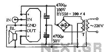
The D amplifier circuit operates by employing a series fool manifold, which facilitates efficient audio amplification. The mono OTL configuration, as represented in Figure 3-12, allows for a simplified design that eliminates the need for output transformers, thereby enhancing audio quality by minimizing distortion and improving frequency response. The wiring diagram illustrates the connections necessary for a single-channel output, ensuring that the amplifier can deliver high-quality audio signals without the drawbacks associated with traditional transformer-based designs.
In the case of the mono OCL amplifier, depicted in Figure 3-13, the circuit is designed to operate with both positive and negative power supplies. This configuration is advantageous as it allows for a broader dynamic range and improved performance in audio applications. The wiring diagram provides a clear representation of the necessary connections to achieve optimal performance in this setup.
For applications requiring dual-channel amplification, the use of two power amplifier modules is essential, as shown in Figure 3-14. This configuration allows for stereo sound reproduction, enhancing the listening experience by providing distinct left and right audio channels. The typical application wiring diagram illustrates how to connect the modules to utilize both positive and negative power supplies effectively, ensuring balanced audio output across both channels.
Overall, the D amplifier's design and configurations cater to various audio amplification needs, providing flexibility for both mono and dual-channel applications while maintaining high audio fidelity and performance.D amplifier uses a series fool manifold. Can easily organize a mono OTL or OCL audio power amplifier, Figure 3-12 is a single-channel power output Typical application wiring diagram OTL. Figure 3-13 for the positive and negative power mono ocl, the output of a typical application wiring diagram. For dual-channel amplifier circuit lap, you need to use two power amplifier module q fool Figure 3-14 is the use of positive and negative power of two-channel output Typical application wiring diagram ocl-
Related Circuits
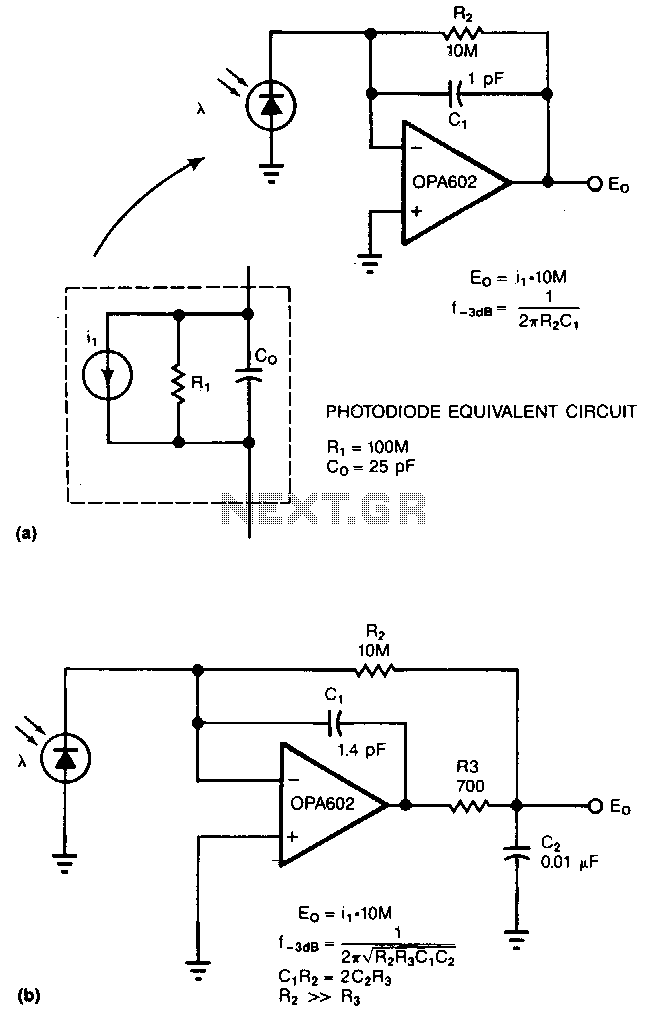
Adding two passive components to a standard photodiode amplifier reduces noise. Without the modification, the shunt capacitance of the photodiode reacting with the relatively large feedback resistor of the transimpedance (current-to-voltage) amplifier creates excessive noise gain. The improved circuit...
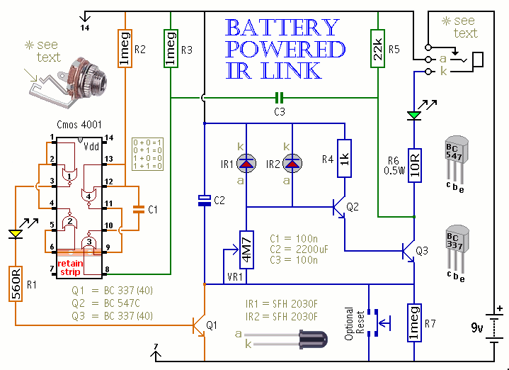
This is a battery-powered infrared (IR) link that can be utilized in multiple rooms. The standby current is exceptionally low, resulting in excellent battery life. The circuit is designed to shut down when faced with extraneous IR radiation, effectively...
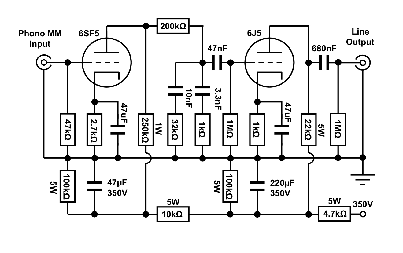
An octal preamplifier can be constructed as a standalone unit without the linestage component. However, this is not feasible due to its split RIAA configuration, which divides the RIAA equalization circuit into two sections: one following the first stage...
Feedback in a public address amplifier should be avoided. The ideal solution is to adjust the positions of the microphone and speaker; however, this is not always feasible in many situations. A frequency shifter that alters the output frequency...
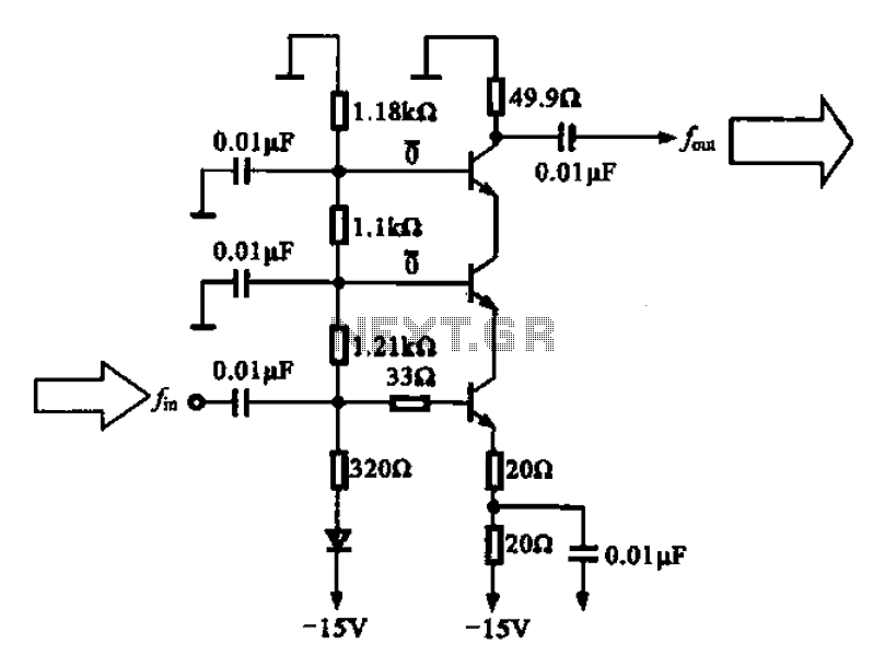
A back radiation small buffer amplifier is presented, featuring an inverse radiation small buffer amplifier configuration. The circuit is composed of three transistors connected in series, functioning as a buffer amplifier. This design can be utilized in output amplifiers...
An additional push-button switch is typically required for the ATX Power Switch/Soft Power Switch signal; however, this simple circuit eliminates that need. The design is effective and has undergone extensive testing. A zener diode is included to protect against...