
Super-Simple Shortwave Receiver Circuit
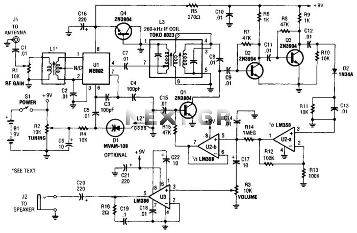
The NE602 integrated circuit serves as a versatile component in RF applications, particularly in communication systems where mixing and frequency conversion are essential. The circuit begins with the reception of RF signals via the antenna input at Jl. The DC-blocking capacitor C1 ensures that any DC component is removed from the incoming signal, protecting the subsequent stages from unwanted biasing effects. The RF gain control resistor Rl allows for adjustment of the gain of the incoming RF signal, enabling optimization of signal strength before it enters the mixer.
The local oscillator, which is critical for the mixing process, is determined by the settings of R2 and L2. The frequency generated here is mixed with the incoming RF signal in the NE602, producing an output that contains both the sum and difference frequencies of the input signals. The desired IF signal, centered around 260 kHz, is isolated using the band-pass transformer L3, which selectively allows the appropriate frequencies to pass while blocking others.
After the mixing stage, the IF signal is amplified by transistors Q2 and Q3, which serve to enhance the signal strength for further processing. The detection of the audio signal from the AM modulation is achieved through diode D2, which rectifies the AM signal, enabling the extraction of the audio component while filtering out the RF carrier frequency. This process is crucial for demodulating the signal for audio playback.
The preamplification stage utilizes Ul-a, a section of the LM358 dual op-amp, to boost the audio signal to a suitable level for driving the final audio amplifier. The LM386, a low-voltage audio power amplifier, is employed to further amplify the audio signal to a level adequate for driving speakers, ensuring that the output is loud enough for listening applications. This combination of components, from RF signal reception to audio amplification, illustrates a comprehensive approach to processing AM signals in electronic communication systems. Integrated circuit Ul (an NE602 double-balanced mixer) is a combination oscillator and frequency mixer. Signals from the antenna input (at Jl) are fed through dc-blocking capacitor C1 to the RF-gain control, Rl, and fed to the input of Ul at pins 1 and 2.
The local-oscillator frequency, which varies with the settings of R2 and L2, is mixed internally within Ul, resulting in an output. The mixer output at pin 4 of Ul is applied to a tunable 260-kHz band-pass intermediate-frequency (IF) transformer, L3, tlirough dc-blocking capacitor C7.
Therefore, signals that are roughly 260 kHz above and below the local-oscillator frequency are passed while others are effectively blocked. The IF frequencies are now amplified by Q2 and Q3. The AM audio signal is detected by D2 and its associated components, which bypass the RF signals, and leave only the audio signals.
The signals are preamplified by Ul -a (half of an LM358 dual op amp). The audio is then boosted to speaker level by the LM386 low-voltage audio power amplifier, U3. 🔗 External reference
Related Circuits
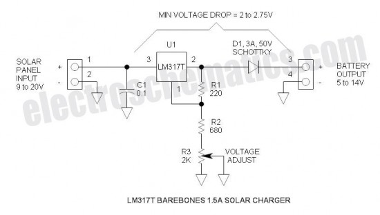
This is the simplest and most affordable solar battery charger that a hobbyist can create. It has some drawbacks compared to other similar controls, but offers unique advantages. The solar battery charger circuit is designed to harness solar energy to...
The schematic diagram of the MS Decoder may appear complex, but it is relatively straightforward. Initially, both the Mid and Side signals are buffered using unity gain inverting buffers, which are constructed around IC1b and IC2b. This buffering serves...
This audio processor circuit features the SSM2045 integrated circuit (IC), designed specifically for electronic music applications, along with the 741 operational amplifier (op-amp) IC. The circuit is configured as a low-pass filter with a DC voltage control for gain....
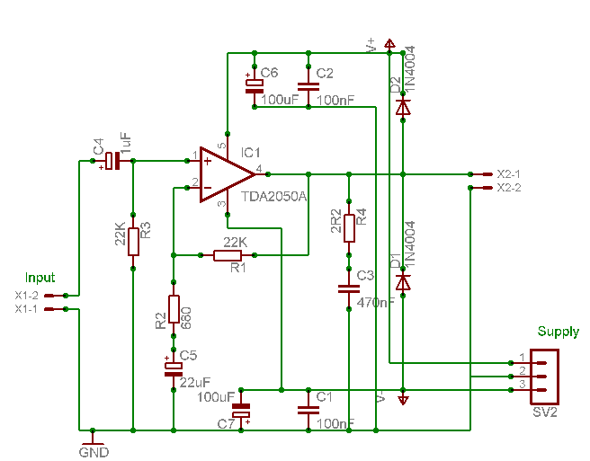
A careful examination of the amplifier photos reveals that the heatsink on the HY60 near-clone built using the TDA2050A is slightly shorter than that of the original HY60s. This unit is positioned at the rear of the amplifier, creating...
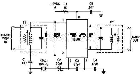
This simple frequency converter mixes the 15-MHz WWV/WVH signal with a 16-MHz signal from the local oscillator (LO) to convert it down to 1 MHz, enabling it to be received on an AM-band receiver. The frequency converter operates by utilizing...
Amplifier with IC number TDA7293 for processing sound systems. This amplifier includes inputs for a radio, TV, stereo, or other line-level devices. It also features a phono input for a record player, guitar, microphone, or other unamplified sources. With...