
Supercapacitor charger electronic circuit using LTC3625
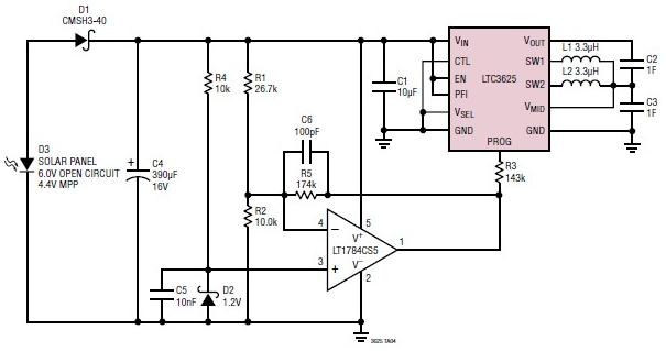
The LTC3625 is a high-performance buck-boost converter designed specifically for supercapacitor charging applications. Its ability to operate over a wide input voltage range makes it suitable for various power sources, including batteries and solar panels. The device's efficiency is critical, as it ensures that most of the input power is converted into usable output energy, minimizing losses during the charging process. The fixed output voltage selection allows for flexibility in applications, enabling the user to adapt the circuit to different supercapacitor configurations.
The automatic cell balancing feature of the LTC3625 is particularly advantageous, as it ensures that both supercapacitors charge equally, thus extending their lifespan and maintaining performance. This is achieved without the need for external balancing resistors, which can introduce additional complexity and power loss. Instead, the LTC3625 internally manages the balancing process, allowing for a more compact and efficient design.
The choice of an LT1784 operational amplifier in this circuit further enhances performance. The LT1784 is known for its low offset voltage and low noise characteristics, making it ideal for precision applications where accurate voltage levels are crucial. This op-amp can be used in feedback loops or signal conditioning stages within the circuit, contributing to the overall stability and reliability of the supercapacitor charging process.
Overall, this supercapacitor charger circuit is a robust solution for energy storage applications, combining high efficiency, ease of use, and minimal component requirements. The design is particularly suited for renewable energy applications, such as solar energy systems, where effective energy storage is essential for continuous power supply. The simplicity of the circuit allows for easy integration into various projects, making it an excellent choice for both hobbyists and professionals in the field of electronics.A very simple supercapacitor charger electronic project can be designed using the LTC3625 IC designed by Linear technology to charge two supercapacitors in series to a fixed output voltage (4. 8V/5. 3V or 4V/4. 5V selectable) from a 2. 7V to 5. 5V input supply. Automatic cell balancing prevents overvoltage damage to either supercapacitor while maximizi ng charge rate without using any balancing resistors. This electronic circuit project presented in this circuit diagram has high efficiency, high charging current, low quiescent current and require low minimum external parts Charging current/maximum input current level is programmed with an external resistor. When the input supply is removed and/or the EN pin is low, the LTC3625 automatically enter a low current state, drawing less than 1 A.
The circuit is very simple requiring few external electronic parts, excepting the LTC3625 IC and solar panel this circuit project require a LT1784 op amp and some common external parts. 🔗 External reference
Related Circuits
The 1N4001 is a 1 Amp silicon rectifier with a voltage range of 50 to 1000 volts. It features guaranteed high-temperature soldering, high current capability, a diffused junction, low reverse leakage, and utilizes a void-free molded plastic technique for...
This circuit originates from a 14-watt commercial electric spiral bulb from Home Depot. The layout is commendable and credit is due to Sam Goldwasser for its design. The circuit features an interesting oscillator configuration, which will be explained in...
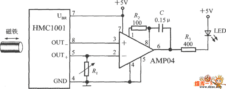
The image depicts a proximity switch circuit that includes the HMC1001 Hall effect sensor, an operational amplifier (AMP04), and a light-emitting diode (LED). In this configuration, the operational amplifier functions as a comparator. When a magnet with a length...
The overhaul includes features such as online judge diodes, the ability to test whether transistors are functioning properly, and the capability to assess TTL logic levels or high impedance states. It can output signals at 37 MHz, bar television...
The purpose of this circuit is to animate shop windows using a capacitive sensor positioned behind a postcard-like banner. The card is placed against the glass inside the shop window, allowing visitors to activate the relay by placing their...
A simple calling bell circuit designed for small offices to summon the office boy using an existing intercom system. The office boy can be called from up to nine locations equipped with extension lines. The system connects to a...