Proximity Switch Circuit Composed Of Integrated Magnetic Sensor HMC1001
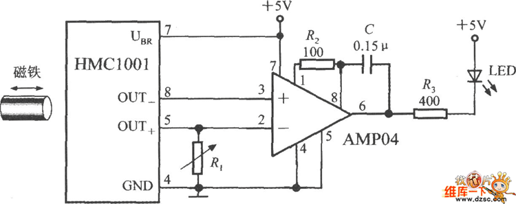
The image depicts a proximity switch circuit that includes the HMC1001 Hall effect sensor, an operational amplifier (AMP04), and a light-emitting diode (LED). In this configuration, the operational amplifier functions as a comparator. When a magnet with a length of approximately 6mm to 12mm is brought close to the HMC1001, the output voltage of the MR electric bridge will change to around 30mV at a specific position.
The proximity switch circuit operates through the integration of the HMC1001 Hall effect sensor, which detects the presence of a magnetic field. The sensor generates a small voltage output proportional to the magnetic flux density it experiences. In this setup, when a magnet is brought within the effective range of the HMC1001, the sensor detects the magnetic field and produces a corresponding output voltage.
The operational amplifier (AMP04) is configured as a comparator to process the output signal from the HMC1001. This comparator compares the sensor's output voltage against a pre-defined reference voltage. When the output voltage from the HMC1001 exceeds this reference level, the operational amplifier switches its output state. This transition can be used to drive the LED, indicating the presence of the magnetic field.
The LED serves as a visual indicator of the sensor's activation, illuminating when the magnet is within the specified range. The circuit design allows for a simple yet effective method of detecting magnetic proximity, making it suitable for applications such as object detection, security systems, and automation tasks.
The overall design ensures that the circuit remains compact and efficient, with the HMC1001 providing sensitive detection capabilities and the AMP04 enabling precise signal processing. The choice of components allows for reliable operation in various environments, making it a versatile solution for proximity sensing applications.The picture shows the proximity switch circuit composed of the HMC1001 and operational amplifier (AMP04) and light emitting diode (LED). The operational amplifier is used as a comparator here. If taking a magnet with length about 6mm~12mm to close to the HMC1001, when it moves to a certain position, the MR electric bridge`s output voltage would be 30mV to..
🔗 External reference
