
Simple Calling Bell Using an Intercom
The calling bell circuit utilizes a combination of analog and digital components to facilitate communication in a small office environment. The circuit leverages the existing intercom infrastructure, making it cost-effective and easy to implement. The use of DTMF technology allows for reliable and accurate location signaling, ensuring that the office boy can respond promptly to requests for assistance.
The optocoupler MCT2E serves as an interface between the telephone line and the timer circuits, providing electrical isolation and ensuring that the ringing signal does not interfere with the operation of the timers. The NE555 timers are configured in a monostable mode, allowing for precise control over the timing of the ringing cessation and bell activation. The ability to adjust the timing with a variable resistor adds versatility to the circuit, accommodating different office environments and preferences.
The decoder section, built around the MT8870, is crucial for interpreting the DTMF tones generated by the telephone. This IC efficiently converts the dual-tone signals into binary outputs, which are then processed by the driver IC 7447 to drive the seven-segment display. The display provides a clear visual indication of the location number, enhancing user experience and ensuring that the office boy can respond to the correct request.
Overall, the circuit represents a practical solution for improving communication efficiency in small office settings, combining simplicity with effective functionality. Proper assembly and enclosure of the circuit components are essential for durability and ease of use, ensuring that the system operates reliably over time.A simple calling bell circuit that can be used in small offices to call the office boy using an existing intercom system. The office boy can be called from up to nine locations where extension lines are installed. The system is connected to a dedicated extension for the office boy. Whenever someone needs the office boy`s assistance, he can dial the office boy`s extension number through the intercom and then press a key to indicate his location number (say, 5). This number will be displayed on a seven-segment display and at the same time a bell will sound to alert the office boy.
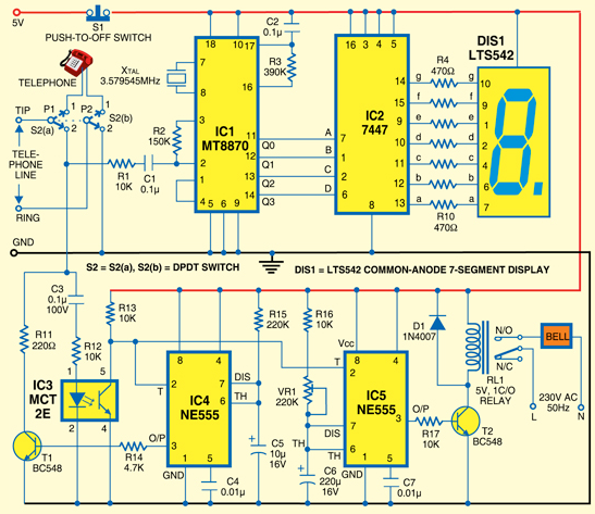
Pressing a switch will clear the display. The ring cease and bell timer section is built around optocoupler MCT2E (IC3), NE555 timers (IC4 and IC5) and a few discrete components. The optocoupler is used to trigger the timers (IC4 and IC5). Both the timers are wired in monostable mode. The time period of IC4 is fixed at 2-3 seconds, while the time period of IC5 can be set from 3 seconds to one minute using preset VR1.
If you want a longer time period, increase the value of capacitor C6 or resistor R16. When someone rings the office boy`s phone, the internal LED of optocoupler IC3 glows, triggering timers IC4 and IC5. The high output of IC4 at its pin 3 makes transistor T1 conduct, putting resistor R11 across the telephone line to cease the ring.
At the same time, the high output of IC5 (pin 3) drives relay RL1 to enable the bell for a preset time period. The decoder cum display section is built around DTMF IC 8870 (IC1), IC 7447 (IC2), common-anode 7-segment display LTS542 (DIS1) and some discrete components.
The main IC of this section is MT8870. It is widely used in telephones and a variety of other applications. The DTMF (dual-tone multi-frequency) tone pair generated by pressing the telephone button is converted into binary values by MT8870. The binary values are fed to driver IC 7447 to display corresponding number on the seven-segment display.
Working of the circuit is simple. Connect the assembled circuit to dedicated extension for the office boy. Connect 5V to the circuit using 5V power adaptor. Now when you dial this dedicated extension number, the ring will cease in a few seconds. After the ring ceases, press a digit on the telephone to indicate your location (say, 5). This number will be displayed on the seven-segment display and the bell will sound for a preset time period to alert the office boy. After providing the assistance to this room, the office boy can wait for the next call. If you want to use the telephone as a regular intercom, simply connect switch S2 to position 1. This will disable the circuit. Now you can dial any extension number through the telephone. If you want to use the call bell again, just turn switch S2 to position 2. Assemble the circuit on a general-purpose PCB and enclose in a suitable cabinet. Fix the connectors to connect the telephone line and AC supply at the rear side of the cabinet. Mount the 7-segment display, buzzer and switch S2 on front side of the cabinet. 🔗 External reference
Related Circuits
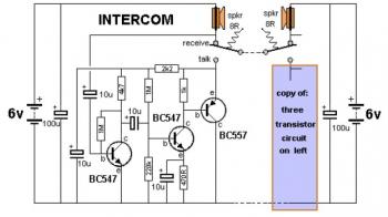
This is a two-station simple intercom circuit built using transistors and common 8-ohm mini speakers. The speaker functions as a microphone and generates sound, eliminating the need for a separate microphone in this intercom setup. The "press-to-talk" switches should...
A low-cost light dimmer utilizing a silicon-controlled rectifier (SCR) and a triac. The flash-on effect is minimized by shunting the SCR with two 20K resistors, as per the guidance of Motorola Semiconductor Products Inc. The described light dimmer circuit...
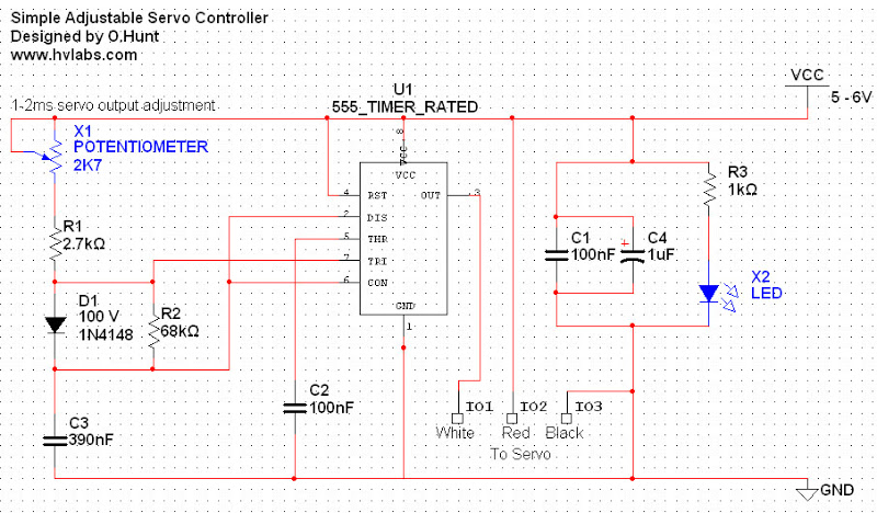
Servos are valuable components for various applications, including robotics, automation, and remote control tasks, such as steering model vehicles. They are relatively inexpensive and readily available; however, controlling them can be somewhat challenging as they require specific timing to...
In this circuit, an NE592 acts as an IF amplifier. DC coupling between mixer and amplifier is practical because different +6 V and +12 V supply voltages are used. The voltage at the differential input is about 4.5 V....
Remote control utilizing VHF modules. Several designs for remote control switches using the VG40T and VG40R remote control pair are presented here. The miniature transmitter module illustrated in Fig. 1. The VG40T and VG40R are VHF radio frequency (RF) modules...
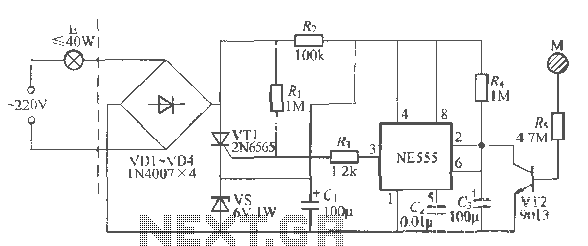
Using a wire connection, utilize the NFA.55 timebase circuit delay type light touch switch, which can directly replace an ordinary mechanical switch without needing to modify the original internal wiring. The circuit is powered back with good hoof Chapter...