
Supercharged Joule circuit
The circuit schematic in question likely includes various electronic components arranged to perform a specific function. Typically, such schematics are used to illustrate the connections and relationships between components like resistors, capacitors, diodes, transistors, and integrated circuits. Each component is represented by standardized symbols, and the connections are depicted by lines that indicate electrical pathways.
In a well-designed schematic, components would be labeled with their values and specifications, such as resistance in ohms for resistors or capacitance in farads for capacitors. The power supply would also be indicated, showing the voltage levels required for the circuit to operate effectively. Ground connections are usually marked to establish a common return path for the current.
Furthermore, the schematic might include additional annotations or notes that clarify the functionality of specific sections of the circuit. For example, it could specify which components are part of a feedback loop, which are responsible for signal amplification, or those that filter out unwanted noise.
Overall, a comprehensive schematic serves as a crucial tool for engineers and technicians, allowing for easier troubleshooting, modification, and understanding of the circuit's operation. It is essential that such documents are accurately prepared and made accessible to ensure that the intended audience can utilize them effectively.I think this picture and schematic was posted to my watsonseblog. but it didnt get posted to this 🔗 External reference
Related Circuits
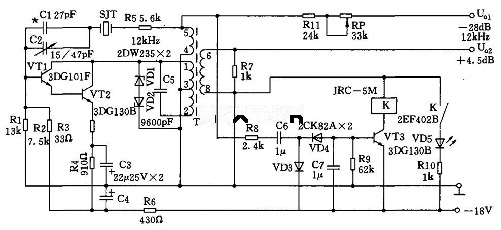
The circuit depicted is a 12 kHz intermediate frequency oscillator designed for an alarm system. It employs a variable feedback oscillation circuit where the oscillation frequency is primarily determined by a quartz crystal. Capacitors C1 and C2 are used...
The following circuit illustrates a 2000W Power Amplifier Circuit Diagram. This circuit utilizes the BC560C transistor. Features include a robust design. The 2000W power amplifier circuit is designed to deliver high output power suitable for various applications, including audio amplification...
The discharge control circuit consists of a battery management system designed to prevent over-discharge of a battery. It features a relay control mechanism that activates when the battery voltage drops below a specified threshold of approximately 10.5V. The circuit...
Charging a mobile phone or cellphone battery presents a significant challenge while traveling, as a power supply source is often not readily available. If the cellphone remains switched on continuously, its battery can deplete within five to six hours,...
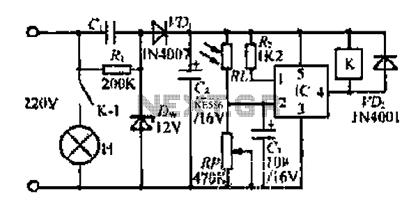
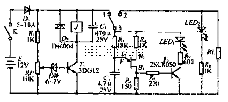
At dawn, light illuminates the photosensitive resistor RL, causing its resistance to decrease. This switch IC (2) exhibits a high electrical footprint. When light is present, the relay K does not activate. At night, in the absence of light,...
In electronic technology, the triode utilizes a variety of general components and parts. The parameters of the triode and numerous electrical parametric measurement schemes are closely related to measurement results. Therefore, in electronic design, the base pin, typological judgment,...