
2000W Power AmplifierCircuit Using The BC560C Transistor
The 2000W power amplifier circuit is designed to deliver high output power suitable for various applications, including audio amplification and RF transmission. The BC560C transistor, which is a PNP bipolar junction transistor, is utilized in this circuit for its ability to handle significant power levels while providing efficient amplification.
The circuit typically consists of a power supply section, input stage, driver stage, and output stage. The power supply must be capable of delivering sufficient voltage and current to support the 2000W output, often requiring a transformer and rectifier setup to convert AC to DC.
The input stage may include capacitors for coupling and DC blocking, ensuring that only the desired signal is amplified while preventing DC bias from affecting subsequent stages. The driver stage is responsible for providing adequate gain to drive the output stage, which consists of the BC560C transistors arranged in a push-pull configuration. This setup allows for efficient amplification of the input signal, with one transistor conducting during the positive half-cycle and the other during the negative half-cycle.
Feedback mechanisms may be employed to improve linearity and reduce distortion, ensuring high-fidelity output. Additionally, heat sinks are often necessary to dissipate the heat generated by the transistors during operation, maintaining optimal performance and preventing thermal overload.
Overall, this power amplifier circuit exemplifies a robust design capable of delivering substantial power output while maintaining signal integrity, making it suitable for demanding audio and RF applications. Proper attention to component selection and thermal management is essential for reliable operation.The following circuit shows about 2000W Power Amplifier Circuit Diagram. This circuit using the BC560C Transistor. Features: hard enough to .. 🔗 External reference
Related Circuits
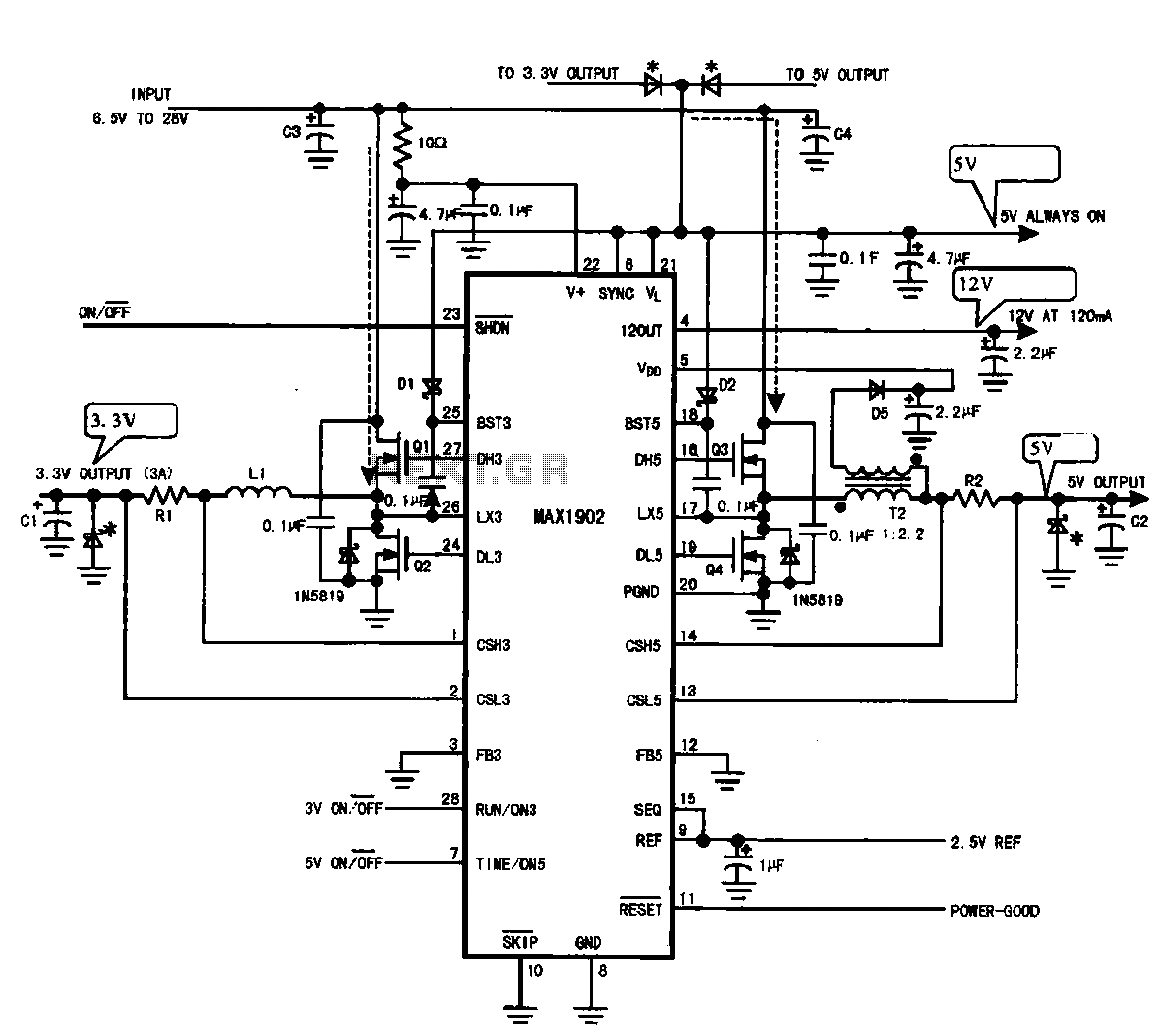
Multi-output power supply circuit (MAX1902). This circuit illustrates the power supply configuration for a notebook computer motherboard, utilizing the MAX1902 chip for power control. It is designed to convert the battery's DC voltage into multiple DC voltage outputs. The multi-output...
Active power factor correction stabilizes the electrical demand of a device to provide optimal power factor characteristics for various types of loads. To comply with power factor regulations, a cost-effective solution should be designed. In many applications, the requirement...

This circuit is a simple metronome model designed for ease of use. It employs transistors as key components, specifically configured as an astable multivibrator, to produce a beeping sound. The tone can be adjusted using a variable resistor (VR1)....
This 5-volt Switch Mode Power Supply circuit utilizes an integrated circuit (IC) from National Semiconductor, which specializes in the production and design of ICs for switch-mode power supply applications. The 5-volt Switch Mode Power Supply (SMPS) circuit is designed to...
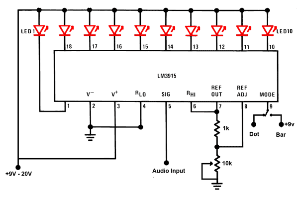
This is a simple audio sound level LED display circuit diagram. The circuit is entirely based on a single integrated circuit, the LM3915 from National Semiconductor. The LM3915 is a monolithic integrated circuit that displays the audio sound level...
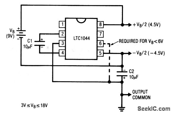
This circuit generates symmetrical ±output voltages, each equal to one-half of the input voltage (for example, a single 9-V battery). The output voltages are referenced to pin 3, which serves as the output common. The circuit is compatible with...
Warning: include(partials/cookie-banner.php): Failed to open stream: Permission denied in /var/www/html/nextgr/view-circuit.php on line 713
Warning: include(): Failed opening 'partials/cookie-banner.php' for inclusion (include_path='.:/usr/share/php') in /var/www/html/nextgr/view-circuit.php on line 713