
Digital tachometer using 8051
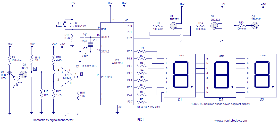
The next component is the signal conditioning unit, which employs an LM324 operational amplifier (IC1). Only one op-amp from the quad LM324 is utilized, configured as a comparator with a reference voltage set at 3.5V using resistors R16 and R17. This comparator converts the spiky collector waveform into a clean square pulse train suitable for input to the microcontroller. Each time the collector voltage of the phototransistor drops below 3.5V, the comparator output saturates negatively, and when it rises above 3.5V, the output saturates positively, resulting in a distinct waveform. The negative-going edges of this waveform indicate the passage of the reflective patch across the sensor, signifying one revolution. The microcontroller measures the number of these negative-going edges occurring within one second to calculate the revolutions per second of the rotating object.
For counting purposes, both timers of the 8051 microcontroller (Timer0 and Timer1) are employed. Timer1 is configured as an 8-bit auto-reload counter to register the incoming zero-going pulses, while Timer0 is set up as a 16-bit timer to generate the necessary one-second time span for Timer1 to count. The assembly code provided initializes the data pointer, sets up the output ports, and configures the timers for counting and display purposes. The main loop includes instructions for loading initial values, starting the timers, and checking for Timer0 rollover. The counting process is repeated until the specified number of counts is reached, after which the display subroutine is called to convert the count into a seven-segment display pattern for visual output.
The tachometer circuit's design emphasizes precision and efficiency in measuring rotational speed, utilizing a combination of optical sensing, signal conditioning, and microcontroller programming to achieve accurate results in real-time applications.A three digit contact less digital tachometer using 8051 microcontroller which can be used for measuring the revolutions/second of a rotating wheel, disc, shaft or anything like that is introduced in this project. The tachometer can measure up to a maximum of 255 rev/sec at an accuracy of 1 rev/sec. What you just need to do is to align the sensor close to the reflective strip (aluminium foil, white paper or some thing like that) glued on the rotating surface and the meter shows the rev/sec on the display. The circuit diagram of the digital tachometer is shown below. The first section of the circuit is the optical pickup based on photo transistor Q4 and red LED D4. Every time the reflective stripe on the rotating object passes in front of the sensor assembly, the reflected light falls on the photo transistor which makes it conduct more and as a result its collector voltage drops towards zero.
When viewed through an oscilloscope the collector waveform of the photo transistor Q4 (2N5777) would look like this: Next part is the signal conditioning unit based on the opamp LM324 (IC1). Only one opamp inside the quad LM324 is used here and it is wired as a comparator with reference voltage set at 3.
5V (using resistors R16 and R17). The job of this comparator unit is to convert the spiky collector wave form into a neat square pulse train so that it can be applied to the microcontroller. Every time the collector voltage of the photo transistor goes below 3. 5V, the output of the comparator goes to negative saturation and every time the collector voltage of the photo transistor goes above 3.
5V, the comparator output goes to positive saturation resulting in a waveform like this: From the above two graphs you can see that the negative going edge of the waveform indicates the passage of the reflective patch across the sensor and that means one revolution. If you could some how measure the number of negative going edges occurring in one second, then that`s the rev/sec of the rotating object and that`s what the microcontroller does here.
For the counting purpose both the timers of 8051 (Timer0 and Timer1) are used. Timer 1 is configured as an 8 bit auto reload counter for registering the number of incoming zero going pulses and Timer0 is configured as a 16 bit timer which generate the necessary 1 second time span for the Timer1 to count. ORG 000H MOV DPTR, #LUT // moves the addres of LUT to DPTR MOV P1, #00000000B // Sets P1 as an output port MOV P0, #00000000B // Sets P0 as an output port MAIN: MOV R6, #14D SETB P3.
5 MOV TMOD, #01100001B // Sets Timer1 as Mode2 counter & Timer0 as Mode1 timer MOV TL1, #00000000B //loads initial value to TL1 MOV TH1, #00000000B //loads initial value to TL1 SETB TR1 // starts timer(counter) 1 BACK: MOV TH0, #00000000B //loads initial value to TH0 MOV TL0, #00000000B //loads initial value to TL0 SETB TR0 //starts timer 0 HERE: JNB TF0, HERE // checks for Timer 0 roll over CLR TR0 // stops Timer0 CLR TF0 // clears Timer Flag 0 DJNZ R6, BACK CLR TR1 // stops Timer(counter)1 CLR TF0 // clears Timer Flag 0 CLR TF1 // clears Timer Flag 1 ACALL DLOOP // Calls subroutine DLOOP for displaying the count SJMP MAIN // jumps back to the main loop DLOOP: MOV R5, #100D BACK1: MOV A, TL1 // loads the current count to the accumulator MOV B, #100D DIV AB // isolates the first digit of the count SETB P1. 0 ACALL DISPLAY // converts the 1st digit to 7 seg pattern MOV P0, A // puts the pattern to Port 0 ACALL DELAY // 1mS delay ACALL DELAY MOV A, B MOV B, #10D DIV AB // isolates the secong digit of the count CLR P1.
0 SETB P1. 1 ACALL DISPLAY // converts the 2nd digit to 7 seg pattern MOV P0, A ACALL DELAY ACALL DELAY MOV A, B // moves the last digit of the count to accumulator CLR P1. 1 SETB P1. 2 ACALL DISPLAY // converts the 3rd digit to 7 seg pattern MOV P0, A ACALL DELAY ACALL DELAY CLR P1. 2 DJNZ R5, BACK1 // repeats the subroutine DLOOP 100 times RET DELAY: 🔗 External reference
Related Circuits
Some time ago, a 1-key keyboard project was developed. The ATTiny microcontroller has been a recurring consideration since then. The 1-key keyboard project utilizes the ATTiny microcontroller, a compact and efficient device suitable for a variety of embedded systems applications....
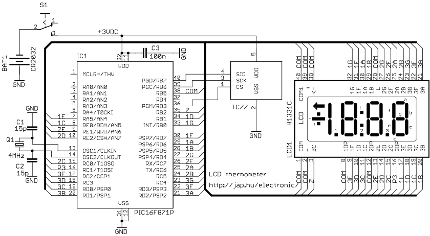
The circuit drives the LCD pins with 50% square waves. Each segment on this LCD is connected to the COM backplane and a separate pin. When a pin is driven in phase with the COM pin, the corresponding LCD...
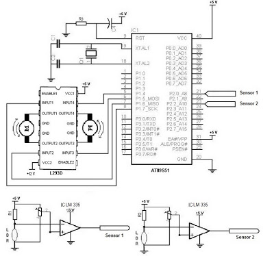
The electronic schematic of the Light Detector Robot can be divided into three main components: the sensor, the microcontroller, and the DC motor driver. The light sensor utilized in this design is a Light Dependent Resistor (LDR), which alters...
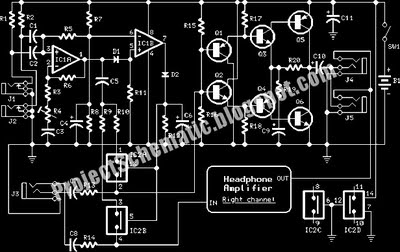
This is a complete circuit designed for an intercom system, which is illustrated in the accompanying diagram. The circuit utilizes a microphone amplifier based on IC1A, featuring two integrated circuits: the LM358, a low-power dual operational amplifier, and either...
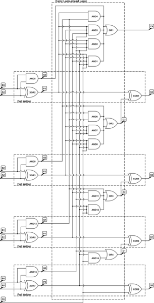
A 4-bit Carry Look Ahead Adder has 3 gate delays for all carry bits and 4 gate delays for all sum bits, whereas ripple adders have 7 and 8 gate delays, respectively. The 4-bit Carry Look Ahead Adder (CLA)...
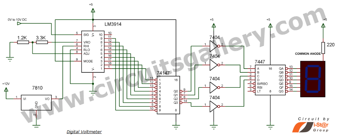
This document explains how to construct a voltmeter for measuring DC voltage without utilizing a multimeter. It describes a straightforward digital voltmeter circuit capable of measuring voltages ranging from 0V to 9V. The primary component of this circuit is...