
Solar powered battery charger using LTC4071
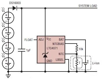
The LTC4071 is a highly efficient integrated circuit designed for charging lithium-ion and lithium-polymer batteries using solar energy. The circuit operates by utilizing photovoltaic cells to convert sunlight into electrical energy, which is then used to charge the battery. The LTC4071 regulates the charging process, ensuring that the battery is charged to the optimal float voltage of 4.1V. This is achieved through an internal shunt mechanism that diverts excess current away from the load when the battery reaches full charge, thus preventing overcharging.
In the event that the photovoltaic cells are unable to provide sufficient current, the LTC4071 allows the battery to supply power to the load, maintaining a stable output voltage at VCC. To safeguard the battery against potential damage from reverse current flow, a diode is incorporated in series with the photovoltaic cells. This diode acts as a one-way valve, ensuring that current can only flow from the solar cells to the battery and not in the opposite direction.
Moreover, the LTC4071 features a low battery disconnect (LBD) function, which is critical for protecting the battery from over-discharge. When the battery voltage drops below the set threshold of 3.2V (with LBSEL connected to ground), the LTC4071 will disconnect the load from the battery. This feature is essential for prolonging the lifespan of lithium-based batteries, as deep discharges can lead to irreversible damage.
Overall, this solar-powered battery charger circuit is an efficient and reliable solution for applications where renewable energy sources are preferred, providing a sustainable method for maintaining battery charge while ensuring the longevity of the battery through careful voltage management and protective features.A simple Solar powered battery charger, photovoltaic charger circuit can be designed using LTC4071 Li-Ion/Polymer Shunt Battery Charger System with Low Battery Disconnect. When VCC reaches the programmed float voltage (4. 1V with ADJ floating) then the LTC4071 shunts excess current not used by the load, limiting VCC to 4.
1V and effectively reduci ng the battery charge current to zero. If the photovoltaic cells stop supplying current, the battery supports the load at VCC through the LTC4071. Add a diode in series with the photovoltaic cells to prevent reverse leakage of the photovoltaic cells from draining the battery.
If the battery discharges to the point where VCC falls below VLBD (3. 2V with LBSEL tied to GND) the LTC4071 disconnects the load from the battery to protect the battery from over discharge. 🔗 External reference
Related Circuits
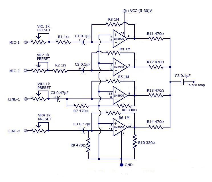
The circuit includes a quad channel amplifier (LM3900) with microphone audio inputs and direct line inputs. By adding circuits in parallel, the number of inputs can be increased for various applications. The input is connected to the inverting terminal...
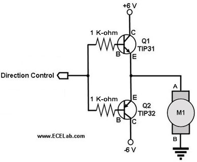
The following circuit illustrates a two-transistor DC motor driver circuit diagram. This circuit utilizes the TIP32 transistor. Features: operates in... The two-transistor DC motor driver circuit is designed to control the operation of a DC motor using two NPN transistors,...
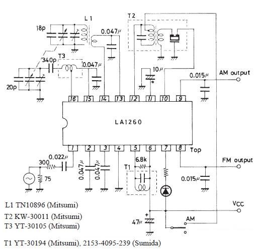
A very simple FM IF MW radio receiver circuit can be designed using the LA1260 IC manufactured by Sanyo Semiconductor. This FM IF MW radio receiver circuit schematic shows that the LA1260 IC can be utilized in AM and...
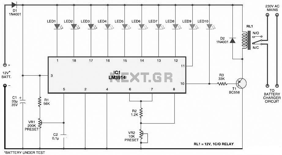
This document presents a circuit diagram for a simple and easy-to-construct battery level indicator. Typically, in mobile phones, battery levels are shown in either dot or bar format, allowing users to easily recognize the battery status. The battery level indicator...
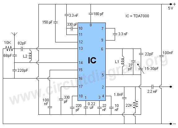
The TDA7000 is a well-known FM radio receiver integrated circuit (IC), also referred to as a one-chip FM radio receiver. It operates within the VHF FM band, covering frequencies from 70 to 120 MHz. Introduced in the 1980s, the...
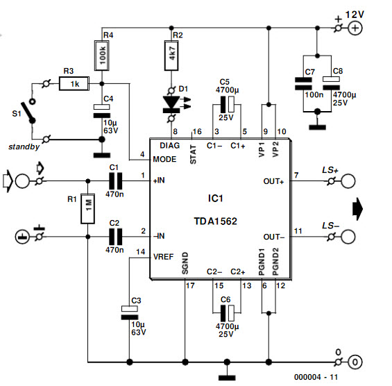
The integrated output amplifier presented in this article consists primarily of a single integrated circuit. It is specifically designed for application in motor vehicles and other battery-operated devices. Despite its seemingly simple design, the amplifier is capable of delivering...
Warning: include(partials/cookie-banner.php): Failed to open stream: Permission denied in /var/www/html/nextgr/view-circuit.php on line 713
Warning: include(): Failed opening 'partials/cookie-banner.php' for inclusion (include_path='.:/usr/share/php') in /var/www/html/nextgr/view-circuit.php on line 713