
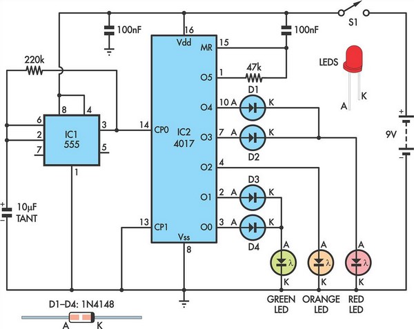
Switch Timer For Bathroom Light
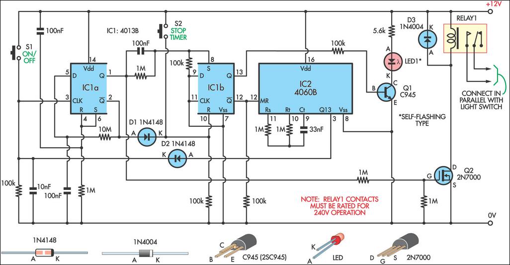
The circuit operates as follows: upon pressing switch S1, the first flip-flop (IC1a) toggles its state, which in turn energizes FET Q2. This action activates the relay, allowing current to flow to the light fixture. If S1 is pressed again within the designated period, IC1a toggles back, deactivating FET Q2 and turning off the relay, thus cutting power to the light.
Should the user desire continuous lighting without the timer, pressing S2 within the 9-minute timeframe disables the timing function, allowing the light to remain on until S1 is pressed again. This feature is particularly useful in scenarios where extended illumination is required without the risk of the light turning off unexpectedly.
The 4060 oscillator/divider (IC2) provides the timing mechanism for the circuit. It generates a clock signal that is divided down to create the desired 9-minute timing interval. This timing is set by external resistors and capacitors connected to pins 9, 10, and 11, which determine the frequency of the oscillator. The relay used in this circuit should be capable of handling the load of the light fixture while being rated for 250VAC operation to ensure safety and reliability.
In summary, this timer switch circuit effectively combines user control with automatic timing features to manage lighting in a bathroom setting, enhancing convenience while minimizing energy waste. The integration of flip-flops, an oscillator, and a relay allows for a straightforward yet effective design suitable for various applications.This 9-minute timer switch can be used to control the light in a toilet or bathroom. The timer is started by pushing S1 and stopped by pushing S1 again. If you forget to turn it off, the controlled light will go off after nine minutes. If you need the light on continuously non-stop, you need to press S1 (turn on) and then S2 (cancellation of timer ) within 9 minutes and in this case the light will be on until you switch it off with S1. IC1 is a is 4013 dual flip-flop. Flip flop IC1a is toggled on and off by switch S1 and it controls the relay which is switched by FET Q2. IC1a controls IC1b which is connected as an RS flipflop to enable or disable IC2, a 4060 oscillator/divider.
This has its timing interval set by the components at its pins 9, 10 & 11. The relay should have 250VAC mains-rated contacts and these are connected in parallel with an existing wall switch. 🔗 External reference
Related Circuits
Auto repair questions concerning brake light issues for the Jeep Grand Cherokee. The Jeep Grand Cherokee features a complex electrical system that integrates various components responsible for the operation of the brake lights. When troubleshooting brake light problems, it is...
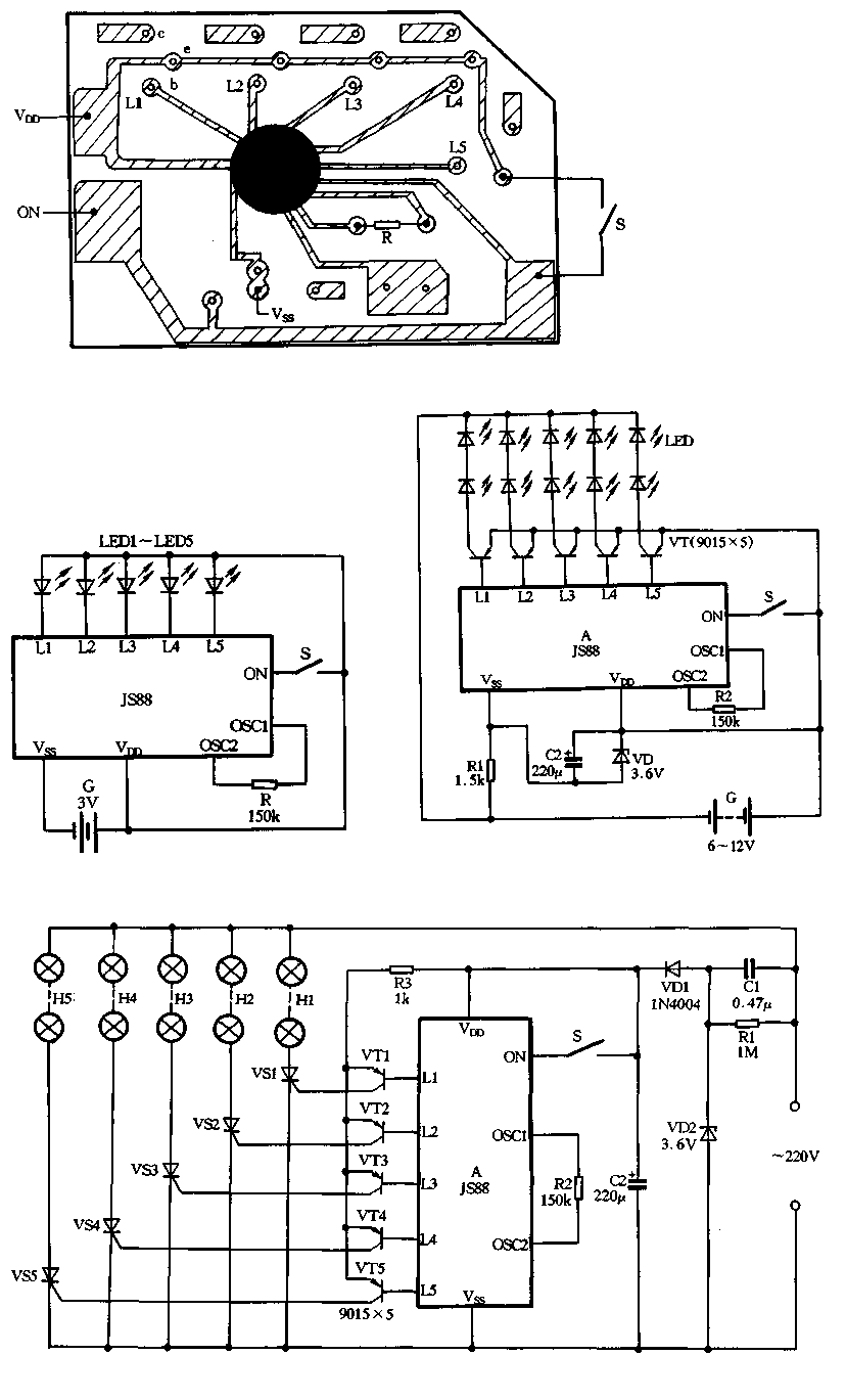
Figure 2-39 illustrates a typical application circuit for the JS88 manifold, which includes an oscillation resistor (R) that allows for fine-tuning of the water flicker frequency. When switch (S) is closed, components L1 to L5 sequentially output low signals...
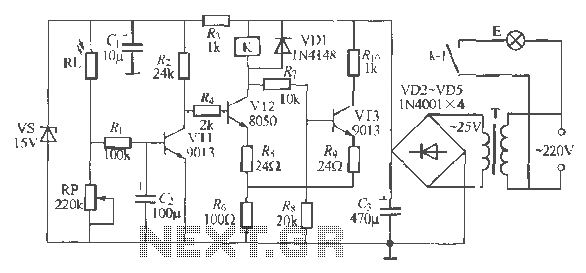
The circuit operates as a light-activated switch that controls white moving lights. It features high sensitivity, stable performance, and good anti-interference characteristics. A photosensitive resistor (RI) is employed to detect ambient light levels. During the day, the resistor exhibits...
Children today appear to possess nearly all the items available in toy stores. Therefore, if there is a son or grandson with a collection of toy cars, here is a suggestion for an addition to that collection. For enhancing a...
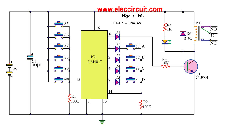
This key code switch circuit is an electronic circuit designed to replace conventional key switches, eliminating the need for physical key inserts. The key code switch circuit utilizes a microcontroller or a dedicated integrated circuit (IC) to interpret key codes entered...
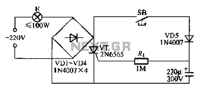
This circuit is a simple connection delay lamp circuit. When the lights are turned on and the switch is pressed, the power supply is activated. The capacitor charges rapidly, causing the thyristor (VT) to open, which in turn lights...