
Key code lock switch circuit
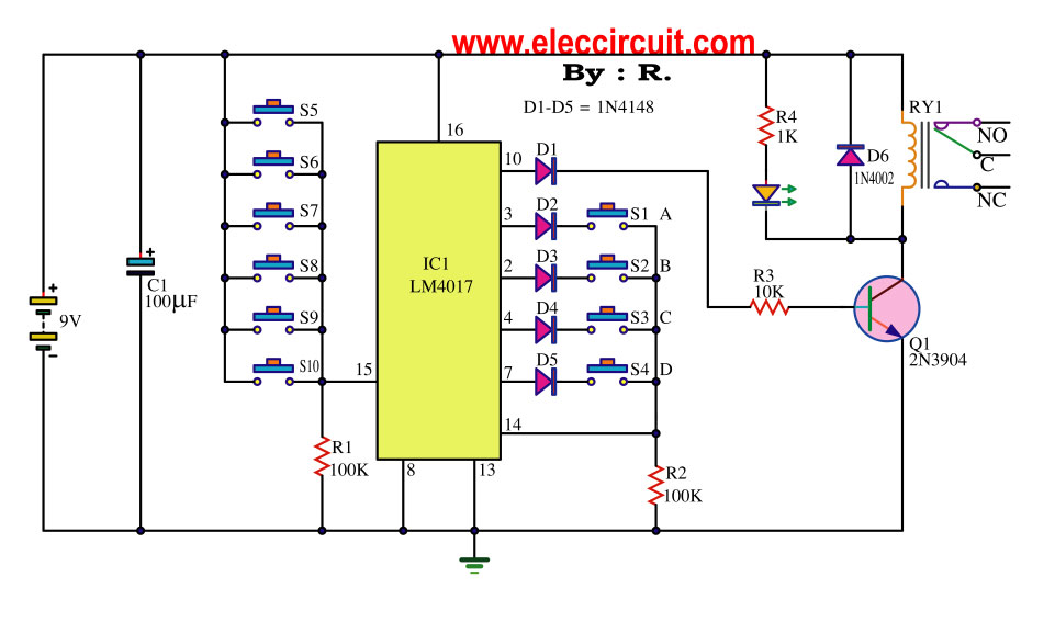
The key code switch circuit utilizes a microcontroller or a dedicated integrated circuit (IC) to interpret key codes entered by the user. This method enhances security and convenience, as it allows for various functionalities without the physical wear and tear associated with traditional mechanical switches.
Typically, the circuit comprises a keypad interface, which may consist of a matrix of buttons or a touch-sensitive surface. When a user inputs a code, the circuit processes the input through a digital signal processor or microcontroller, which compares the entered code against a pre-stored code in its memory. If the entered code matches the stored code, the circuit triggers an output signal that can activate or deactivate a connected device, such as a lock, alarm, or any electronic system requiring authentication.
Power supply requirements for this circuit are generally low, often allowing it to operate on standard batteries or a low-voltage power source. Additionally, the circuit may include features such as LED indicators to provide visual feedback on the status of the key code entry, ensuring the user is aware of successful or failed attempts.
In terms of security, the implementation of a key code switch circuit can incorporate features like timeout periods after multiple failed attempts, making it more difficult for unauthorized users to gain access. Furthermore, some designs may allow for the code to be changed periodically, adding an additional layer of security.
Overall, the key code switch circuit represents a modern solution for secure access control, combining user-friendly design with advanced electronic functionality.This key code switch circuit is a type of electronic circuit that is created to replace conventional normal key switch. Without inserts a keys. But you can.. 🔗 External reference
Related Circuits
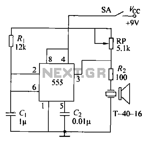
The circuit comprises an ultrasonic transmitter and a T-4 0-16 555 timer circuit. By adjusting the potentiometer RP, the frequency of the oscillation circuit can be modified. The circuit emits ultrasonic signals at a frequency of 40 kHz, with...
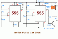
The 555 timer on the right is configured as an alarm sound generator, while the second 555 timer on the left operates as a 1 Hz astable multivibrator. The output from the left timer modulates the frequency of the...
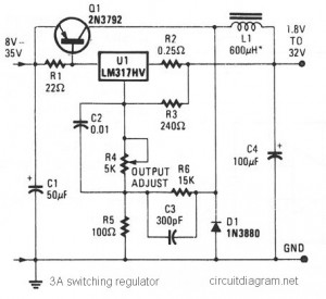
The circuit diagram presented is a simple and cost-effective switching voltage regulator capable of delivering an adjustable output voltage range from 1.8V to 32V with a maximum static current of 3A. This regulator utilizes the adjustable LM317HV IC along...
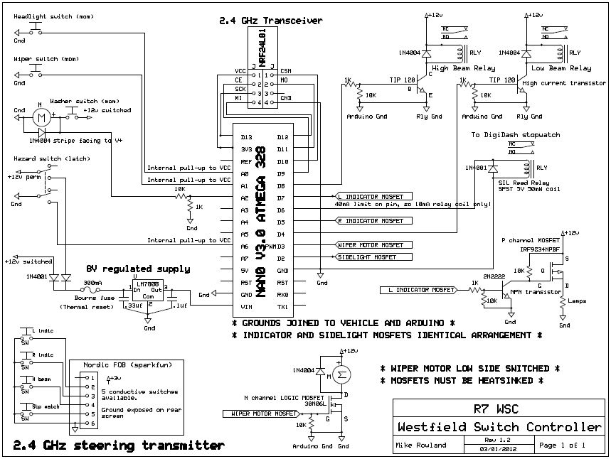
The core of the switch controller is an Arduino Nano microcontroller, which will serve as the interface between the dashboard switches, wireless steering wheel buttons, and the vehicle's lighting, indicators, windscreen wipers, and DigiDash2 GPS stopwatch. This setup facilitates...
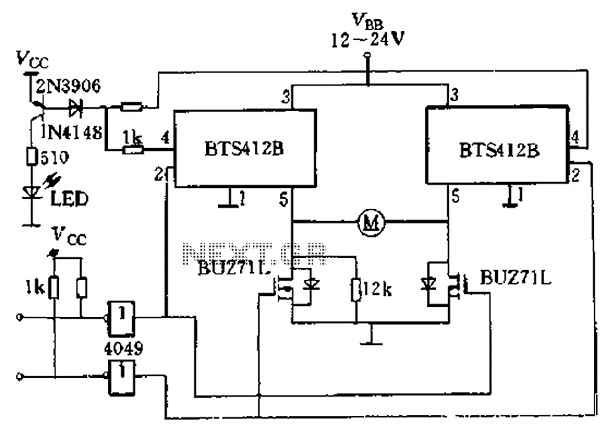
The BTS412B functions as two high-side power MOSFET switches, while two BU271L (50V, Zhang 1n) serve as low-side switches, forming a bi-directional H-bridge DC motor drive circuit. This configuration is designed for electrical automatic door systems, capable of handling...
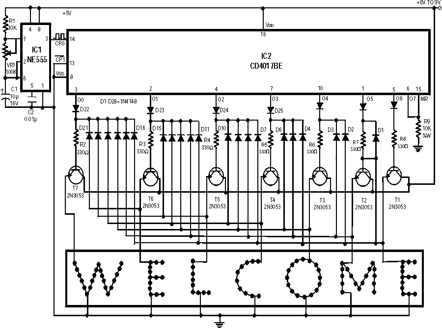
Running Message Display Circuit Diagram. This circuit is based on the CD401 IC. Features: Light emitting diodes are advantageous due to their smaller size. The Running Message Display Circuit utilizes the CD401 integrated circuit, which is a versatile component in...
Warning: include(partials/cookie-banner.php): Failed to open stream: Permission denied in /var/www/html/nextgr/view-circuit.php on line 713
Warning: include(): Failed opening 'partials/cookie-banner.php' for inclusion (include_path='.:/usr/share/php') in /var/www/html/nextgr/view-circuit.php on line 713