
switches Raspberry Pi GPIO
It is essential to address the underlying issues in the question posed, as it demonstrates a lack of experience with electronics. While the individual has formulated a potential solution, they are seeking assistance solely for its implementation while avoiding any information that could lead to alternative approaches. The proposed solution conflicts with fundamental electronics principles, highlighting a need for caution and proper guidance. A suitable analogy is provided to illustrate the risks of proceeding without adequate knowledge, akin to driving under the influence.
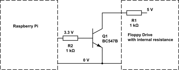
The recommended approach involves placing an appropriate resistor between the transistor and the +5 V line to limit current and prevent potential short-circuits that could damage the driver. However, specific resistor values cannot be suggested without further details about the circuit. Additionally, the transistor must be appropriately rated to handle the current, provide low impedance, and switch rapidly. The suggestion of using a MOSFET is made, as they can handle higher currents and dissipate less power compared to NPN transistors. While an NPN transistor may also suffice, it is crucial to use a resistor to control the current from the GPIO pins of the Raspberry Pi, which can only supply limited current. Without knowledge of the specific transistor being used, it is not possible to provide an accurate recommendation for the base resistor value.
The circuit design involves a stepper motor driver interfaced with a Raspberry Pi, where the GPIO pins control the motor's operation. The step pin, which receives a pulse to advance the motor, is limited to a maximum current of 5 mA. This necessitates careful consideration of the components used in the circuit to avoid damage. The recommendation of a 1 kΩ resistor for the base of the transistor ensures that sufficient current flows to saturate the transistor without exceeding the GPIO pin's current capabilities.
For the direction control, a similar resistor configuration should be implemented to ensure the motor operates correctly without risking damage to the read heads. The design must take into account the voltage ratings and current capacities of the components involved, ensuring that the transistor can handle the expected load without overheating or failing.
In summary, the circuit should incorporate a transistor (either NPN or MOSFET) with a base resistor to control the current from the Raspberry Pi, and additional resistors may be required to limit current to the step and direction control pins. Proper design practices should be followed to ensure that the circuit operates safely and effectively, avoiding shorts and potential damage to the components involved.Experiments with couple of floppy drives I have and it appears that on the step pin, current is limited to around 5 mA. This means that we can indeed omit the collector resistor in this case. For base, I`d recommend a 1 kiloohm resistor. This will give us 3. 3 mA coming into the base of the transistor, which should be more than enough to saturate usual small signal transistors.
Another point worth mentioning here is that same setup will most likely be needed for the direction pin as well, in order to prevent read heads from colliding with end-stops. Some floppy drives have security mechanisms which will prevent the stepper motor from forcing the head when the disk is inserted.
I was about to make a really long comment, but then decided that it`s better to turn it into an answer in hope that you`ll be able to better understand our standpoint. First, you`re being difficult to work with! That may not be obvious to you, so I`ll try to explain: You came to us with a question that looks basic and emits air of someone who isn`t very experienced with electronics.
In your question, you already have some idea for a solution to your problem (which is good, since in general we like it when people post questions they thought about) and then you exclusively ask for help related to implementation of your solution and are avoiding any information that could lead us to provide any other way to accomplish your real objective (which is bad). The problem is that your solution (as you posted it) is in direct conflict with what we got as a part of basic electronics training!
This is NOT a minor thing. I`ll provide an analogy which will hopefully make this a bit easier to understand. Imagine this scenario: You just spend a whole evening drinking alcoholic beverages with your friends and can barely walk in a straight line. Now you`re planing to get in your car and drive back home. While there is a chance that you will be able to get home safely, and it`s true that many have done so in similar circumstances, there is also a great big chance that you will crash and kill yourself (or worse) and possibly someone else as well, making such a plan a bad idea in general.
It`s relatively same with what you`re providing. Sure, it seems that nothing bad is happening when you short the two wires together by hand (just as many drunk people drove safely to their homes), but it doesn`t mean that it`s the proper way to do it (unless we`re really convinced that it`s safe, for which we need details which you refuse to provide believing that your plan is correct). Instead, the proper way to do this (assuming that you just have a simple control line that`s being monitored by stepper motor driver) would be to place an appropriate resistor between the transistor and +5 V line, which will limit the current, so that we don`t have a short-circuit there which could potentially destroy the driver.
Unfortunately, we can`t tell you what type of resistor to use, since we don`t know anything about your circuit and you refuse to provide information. Also the transistor itself needs to be appropriately dimensioned to be able to survive the current, provide low enough impedance to the current`s path and switch quickly enough.
Again we can`t do that without any additional information. Next, in comments I recommended a MOSFET since they can survive greater currents and dissipate less power that NPN transistors. You said that you don`t have a MOSFET and want to use an NPN transistor. It`s quite likely (based on my assumptions at least) that your NPN transistor would work just fine instead of a MOSFET, but for it and the Pi to work fine, you should use a resistor to control the current going from the Pi into the base of the transistor.
Remember, Pi can provide only a little bit of current on its GPIO pins. Without knowing which transistor you have, we can`t give you a good recommendation for the base resistor valu 🔗 External reference
Related Circuits
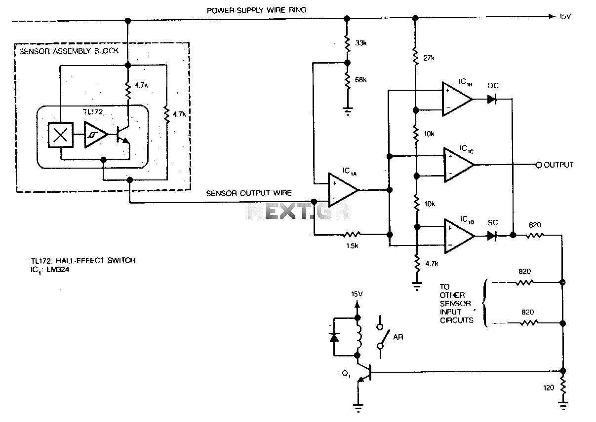
Hall-effect switches have several advantages over mechanical and optically coupled switches. They are insensitive to environmental light and dirt, do not bind, and do not experience mechanical wear. Their major disadvantage is the requirement of three wires per device....
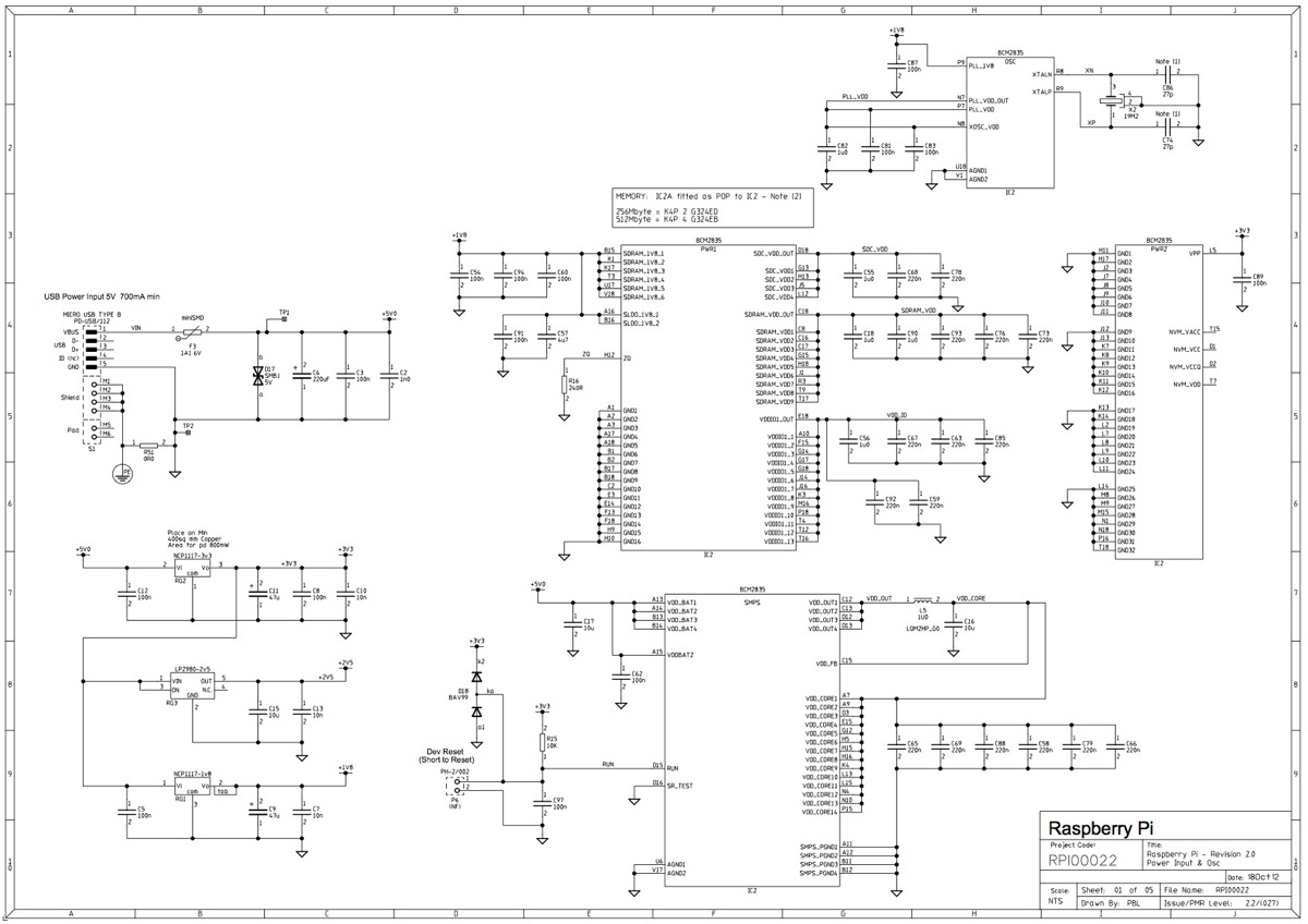
This post outlines the significant modifications implemented in the latest revision of the board. It is important to note that, while the option to incorporate additional signals into the expansion connector has not yet been utilized, developers of expansion...
It can drive up to 128 individual relays, solenoids, motors, fireworks, pyrophones, etc. With a MIDI note-on message you may switch on one of the 128 LEDs (or relays). Outputs may be switched off by sending a note-off message,...
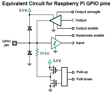
The Raspberry Pi offers general-purpose digital input/output pins, known as GPIO pins, which can be utilized for reading digital logic signals or outputting digital logic levels. Although the output current capability is limited, these pins can effectively drive devices...
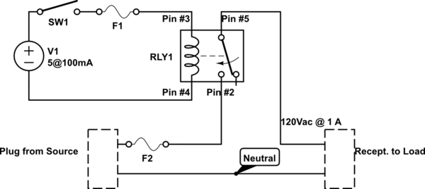
A single-pole double-throw (SPDT) switch is used to control a relay. When the relay is energized, it produces a cycling sound, which is undesirable. The goal is to have the switch operate normally in the 'on' position and return...
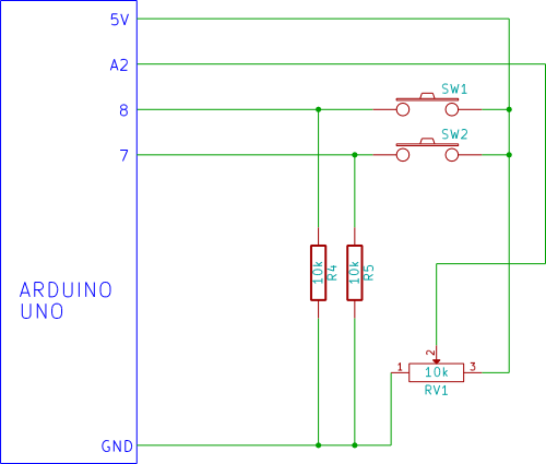
Flicker-free updating of analog input and the status of switches using Ajax and the Arduino Ethernet Shield. The Arduino Uno is configured as a web server. The described system utilizes an Arduino Uno microcontroller, which operates as a web server...