
switches Wiring a SPDT Relay
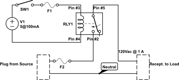
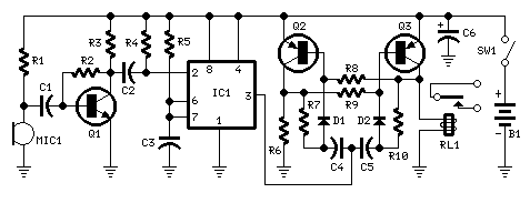
A single-pole double-throw (SPDT) switch operates by connecting a common terminal to one of two outputs, allowing for a choice between two different circuits. In this application, the SPDT switch is utilized to control a relay that manages the flow of current to a load. The relay is designed to switch between two states: normally open (NO) when de-energized and connected when energized.
The relay's operation is described in terms of its pin configuration. When the relay coil is energized, pin #2 becomes connected to pin #5, thus completing the circuit to the load. Conversely, when the relay is not energized, there is no connection between these pins, allowing for the load to be disconnected from the power source. This functionality is critical for applications where the load must be isolated when the relay is not activated.
To implement this in a circuit, it is necessary to break the line wire supplying power to the load. Pin #2 of the relay should be connected to the line wire leading to the load, while pin #5 should connect to the load itself. The neutral wire must remain connected directly to pin #5 to ensure proper operation and safety. This configuration allows for the load to be powered only when the relay is engaged, preventing any undesired cycling noise and ensuring the circuit operates as intended.
In summary, the SPDT switch and relay combination provides a reliable means of controlling electrical devices, with specific attention to the pin connections ensuring safe and effective operation within the specified voltage and current ratings. Proper wiring and understanding of the relay's state transitions are essential for achieving the desired functionality in the circuit design.A SPDT switch that simply switches the relay over. Any pointers would be appreciated. When I currently energize the relay, I hear it cycling, which I would image that is not good. I simple want it to "switch" normally on and then when I energize the coil, switch is back. Take a picture of what you have now (i. e. your wired up breadboard). You will get more better/gooder answers that way. Hair_of_the_Dog Mar 7 `13 at 16:15 Yes, but its not right. I guess for now I am looking for pointers on which pins go where. I know its vague, but like I said, I`m struggling a bit. Phil Vallone Mar 7 `13 at 16:16 So that we can explain why it`s right that way and wrong your way. We`re focused on learning rather than end products. Or at least I am. Camil Staps Mar 7 `13 at 16:34 When the relay is energized (power applied) Pin#2 is connected to pin #5. In the unenergized state pin #2 and Pin #5 are not connected -i. e. they are Normally Open (NO). To wire this into a circuit, (it is rated for 1A at 120V AC) you would break the line wire, and connect the relay pins #2 and #5 inline.
Neutral wire will remain connected. in #5 should go to the load, Pin#2 to the source (for safety reasons). 🔗 External reference
Related Circuits
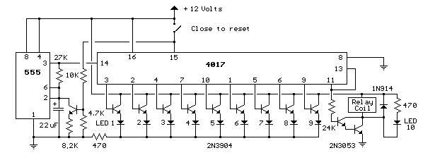
This circuit provides a visual 9-second delay using 10 LEDs before closing a 12-volt relay. When the reset switch is closed, the 4017 decade counter resets to the 0 count, illuminating the LED driven from pin 3. The 555...
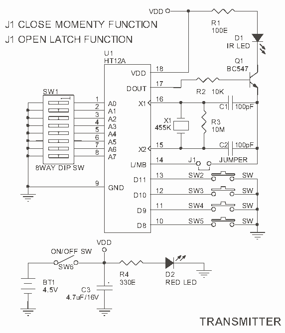
4 Channel Infrared (IR) Remote is a simple kit using the famous HT12A and HT12D encoder/decoder chips from Holtek. The 4 Channel Infrared (IR) Remote system utilizes the HT12A and HT12D integrated circuits to facilitate wireless communication between a transmitter...
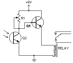
This handy little circuit can tell the difference between darkness and light, making it very useful for switching on and off signs, porch lights or other things when it gets dark or light. More: R1 Adjusts sensitivity The circuit described...
The TS555 is a single CMOS timer that provides low power consumption and high frequency, maintaining accurate timing in both monostable and astable modes. It produces reduced supply current spikes during output transitions, allowing for the use of smaller...
The traditional potentiometer is implemented with an electrical contact that slides over a resistive layer. An example of a well-known audio-grade potmeter is the Alps Blue. A high-end (good and costly) alternative is the rotary switch. This device consists...
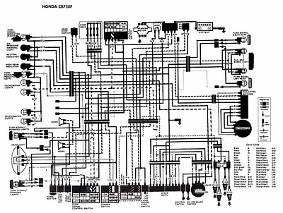
The following image illustrates the electrical wiring connection diagram for the Honda Motorcycle CB750F. It details the connections between various Honda components, including the right turn signal indicator light, oil pressure warning light, neutral indicator, high beam indicator, turn...
Warning: include(partials/cookie-banner.php): Failed to open stream: Permission denied in /var/www/html/nextgr/view-circuit.php on line 713
Warning: include(): Failed opening 'partials/cookie-banner.php' for inclusion (include_path='.:/usr/share/php') in /var/www/html/nextgr/view-circuit.php on line 713