
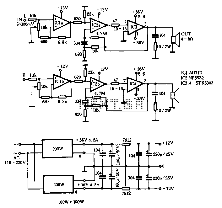
Switching power supply circuit with STK6303
The T amplifier circuit is designed to deliver high power efficiency and sound quality, making it suitable for various audio amplification applications. The STK6303 integrated circuit is known for its robustness and ability to handle significant output currents, which is essential in high-performance audio systems. The maximum supply voltage of 36V ensures that the amplifier can operate effectively without distortion at high output levels.
The incorporation of the AD712 op-amp for volume control enhances the circuit's versatility. This op-amp is known for its low noise and high precision, contributing to the overall fidelity of the audio output. The adjustable gain feature allows users to customize the amplification level based on the input signal, which is particularly advantageous in dynamic audio environments where signal levels may vary.
The use of a potentiometer for gain adjustment allows for smooth transitions in volume control, minimizing abrupt changes that can be jarring in audio applications. The high balance of the potentiometer ensures that both channels of the amplifier maintain equal output levels, which is crucial for stereo applications.
The NE5532, as a driving stage, further enhances the circuit's performance by providing a stable gain structure. Its quasi-second mode of operation allows for better linearity and reduced distortion, which is vital for maintaining audio integrity across a range of frequencies. The specified input sensitivity of 300mV indicates that the amplifier can effectively amplify low-level signals, making it suitable for use with various audio sources, including microphones and line-level devices.
Overall, this T amplifier circuit schematic represents a well-engineered solution for high-fidelity audio amplification, combining high power output, adjustable gain, and low noise characteristics, making it a valuable component in modern audio systems. Careful consideration of impedance matching will ensure optimal performance when interfacing with different audio sources.T amplifier circuit schematic section shown in Figure 3-51 Japan Sanyo STK6303 Pina made high-power thick film integrated circuit, the power supply voltage maximum Dashi sov, output current up to about loA Division monolithic circuit powering Guests 36V, you can get loOw sinusoidal power. In the circuit of negative feedback op amp AD712 volume control ten of its advantages is itself a high-quality adjustable gain (O ~ l0 times) pre-stage, using potentiometer resistance line, high balance, no control procedure noise, very solid with, worthy of promotion. NE5532 as a thick film circuit STK6303 driven stage, is a quasi- second mode, this level gain of about 15 times the input of the amplifier sensitivity 300mV, impedance about lOktl, can be adapted to a variety of common signal source (of course, pay attention to impedance matching Wait).
Related Circuits
The Inter-Power SWR-5 upper right isn't worth a penny. Got it from a mate to use with a beacon, but I burnt it out with only 3.5-4W morse signal on 70cm. Removed the bridge and installed my own pick-up...
This simple circuit is the electronic version of the combination lock. Using the special purpose LS7220 digital lock IC, the circuit allows a 4 digit combination of your choice to activate a relay for a set period of time....
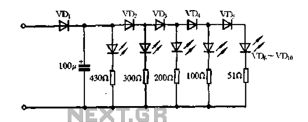
A passive light-emitting diode output level indication circuit. This circuit utilizes a light-emitting diode (LED) to provide a visual indication of the output level from a given source. The design is characterized by its passive nature, meaning it does not...
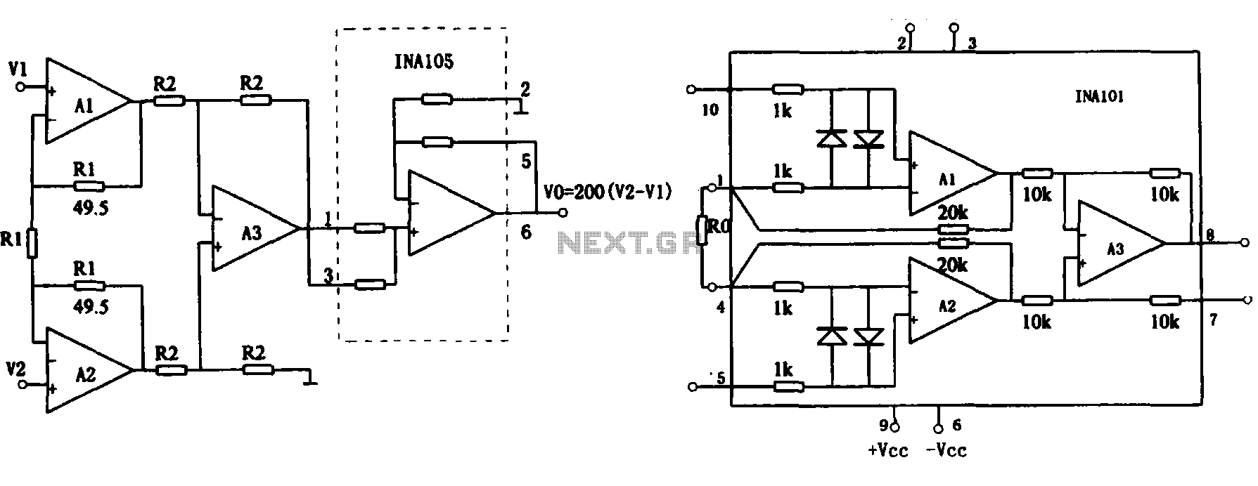
This document describes the extended common mode input voltage range of an instrument amplifier circuit. The circuit consists of three precision instrument amplifiers, A1, A2, and A3, which can be INA101 or INA102 models. The figure illustrates that A1,...
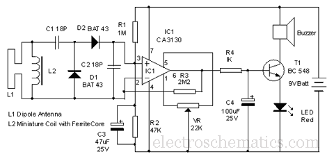
This circuit is designed to detect microwave sources, such as microwave ovens, satellite communication devices, and mobile phones. It provides audio-visual indications when microwaves in the gigahertz band are detected. Microwaves are a form of electromagnetic radiation with frequencies...
In this circuit, a simple calculator, in conjunction with a COB (chip-on-board) from an analogue quartz clock, is used to make a telephone call meter. The calculator enables conversion of STD/ISD calls to local call equivalents and always displays...