
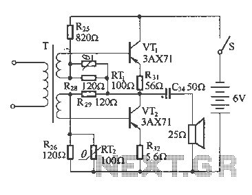
swr metering circuit and ssb transceiver 80m 40m boster filter if radio

The broadband QRP SWR (Standing Wave Ratio) metering circuit serves as an essential tool for amateur radio operators using low-power (QRP) transmitters. This circuit is designed to provide real-time feedback on the impedance matching between the antenna and the transmitter, which is crucial for efficient operation and to prevent damage to the transmitter.
The schematic includes a momentary double-pole double-throw (DPDT) switch that, when pressed, activates the SWR measurement process. The LED indicator is used to visually represent the SWR level: a dim LED indicates a good match (minimum SWR), while a bright LED signals a poor match (high SWR). This feedback allows operators to fine-tune the antenna tuner by adjusting its capacitors.
Key components of the circuit may include resistors, capacitors, and diodes configured to form a voltage divider that translates the RF power levels into a readable format for the LED. The design should ensure that the circuit operates across a broad frequency range, accommodating various amateur radio bands. Additionally, attention must be paid to component ratings to handle the power levels typical in QRP operations without distortion or damage.
Overall, this broadband QRP SWR metering circuit is a valuable addition to any QRP antenna tuner, providing a simple yet effective means of optimizing antenna performance.A schematic diagram for a broadband QRP SWR metering circuit for use in a QRP antenna tuner. One could simply hold a momentary DPDT switch down and watch the LED while tuning the capacitors of the antenna tuner for minimum or zero light. 🔗 External reference
Related Circuits
The following diagram illustrates a common output transformerless (OTL) amplifier circuit that delivers an output power of 100 mW. The circuit includes an output transformer and a capacitor, which work in conjunction with speaker units. The frequency characteristics of...
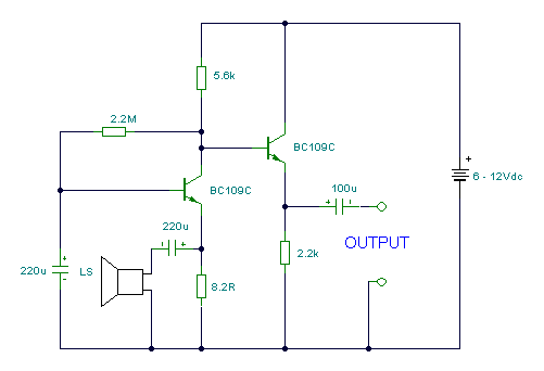
This circuit utilizes a standard loudspeaker, enabling it to function as a microphone. It allows for the use of an inexpensive loudspeaker in this capacity. Sound waves impacting the speaker cone result in variations in the voice coil. The...

The UC3842, UC3843, UC3844, and UC3845 series of oscillators can generate synchronization pulses without requiring numerous external components. The following circuit illustrates the Sync Pulse Generator Circuit Diagram for the UC3842/3/4/5. This sync pulse circuitry is capable of operating...

This design is based on a publication by Milan Lulic in the German magazine elektroModell. Lulic's design utilizes surface mount technology (SMT), while this version employs standard off-the-shelf components, making it more accessible for hobbyists. For those interested in...

The objective of the project is to create a system that utilizes mobile technology to manage various home appliances based on signals sent from a mobile device. This innovative concept allows for the remote control of appliances through GSM...
The mixer can accommodate any number of channels as needed by duplicating the input sections illustrated in the schematic. One instance of this mixer featured 25 inputs. The mixer circuit is designed to provide flexibility in channel configuration, allowing for...