
Loudspeaker to Microphone converter circuit
The second stage is directly coupled and operates in emitter follower mode. Although the voltage gain is slightly less than unity, the output impedance is low, allowing it to drive long cables effectively. While the audio quality may not match that of a standard or electret condenser microphone, reasonably acceptable results can still be achieved. Loudspeakers with cone diameters ranging from 1 inch to 3 inches are suitable, and speaker impedance can vary from 4 ohms to 64 ohms. The value of the 8.2-ohm resistor may be adjusted to correspond with the actual impedance of the speaker.
This circuit design effectively converts a loudspeaker into a makeshift microphone by capitalizing on the transduction properties of the speaker's cone and voice coil. The initial stage employs a common base transistor configuration, which is particularly advantageous for low-impedance sources such as loudspeakers. The common base stage facilitates a high voltage gain while maintaining a low input impedance, which is essential for efficient signal transfer from the speaker to the transistor.
In the second stage, the emitter follower configuration serves to buffer the signal, providing a low output impedance that is capable of driving longer cable runs without significant signal degradation. This characteristic is crucial in practical applications where the microphone may be positioned far from the processing equipment. Despite the limitations in audio fidelity compared to conventional microphones, this circuit can be employed in various applications where cost-effectiveness is prioritized, such as in DIY projects or educational demonstrations.
The versatility of the circuit allows for the use of a range of loudspeakers, accommodating different sizes and impedances. The ability to modify the resistor value to match the loudspeaker's impedance is an important feature, ensuring optimal performance and signal integrity. Overall, this circuit represents an innovative approach to audio signal capture, leveraging readily available components to achieve functional results in sound detection applications.This circuit takes an ordinary loudspeaker and allows it to be used in reverse, as a microphone. This circuits allows you to use a cheap loudspeaker as a microphone.Sound waves reaching the speaker cone cause fluctuations in the voice coil. The voice coil moving in the speakers magnetic field will produce a small electrical signal . The circuit is designed to be used with an operating voltage between 6 and 12 volts dc. The first transistor operates in common base mode. This has the advantage of matching the low input impedance of the speaker to the common base stage, and secondly has a high voltage gain.
The second stage is direct coupled and operates in emitter follower. Voltage gain is slightly less than unity, but output impedance is low, and will drive long cables. Speech quality is not as good compared to an ordinary or ECM microphone, but quite acceptable results can be obtained. Speaker cones with diameters of 1 inch to 3 inches may be used. Speaker impedance may be 4 ohm to 64 ohm. The 8.2 ohm resistor value may be changed to match the actual speakers own impedance. 🔗 External reference
Related Circuits
This is a fun and non-dangerous project for those people who like to throw projectiles magnetically. It simply works by placing a ferromagnetic projectile at one end of a coil and pulsing some power in it. The trick is...
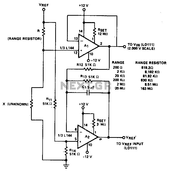
The circuit accurately measures up to 20M when used with a buffer amplifier (Al) that has a low input bias current (IiN) of less than 30 nA. It utilizes two of the three amplifiers found in the Siliconix L144...
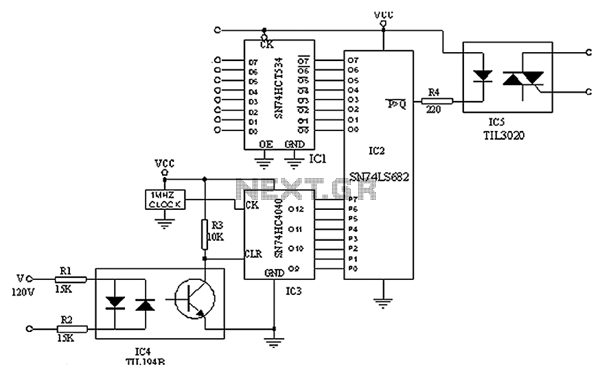
A simple digital circuit is presented that can be used to precisely control the AC power supply. This circuit does not include a digital-to-analog conversion component. In its application, effective control is established through a computer system that sends...
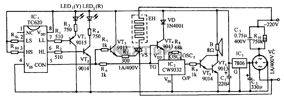
The circuit includes the TC620 temperature control circuit, the temperature indicator circuit, a thyristor-controlled heating circuit, a vocal music buck rectifier circuit, and the AC circuit. The TC620 temperature control circuit is designed to regulate temperature by monitoring the temperature...
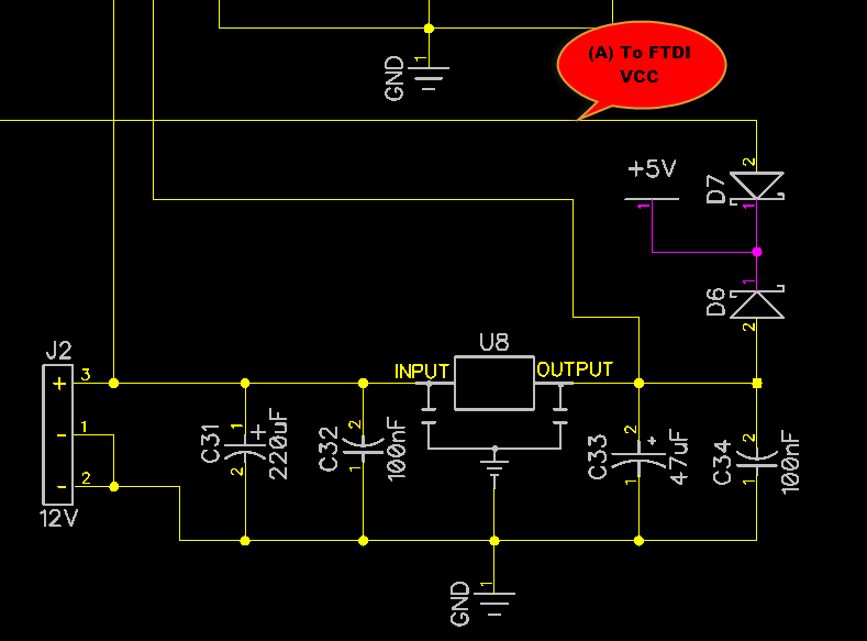
When only the voltage regulator (VR) supplies power to the circuit, the microcontroller unit (MCU) will receive power from the +5V bus, while the FTDI chip will only receive VCCIO. At the midpoint of the voltage divider formed by...
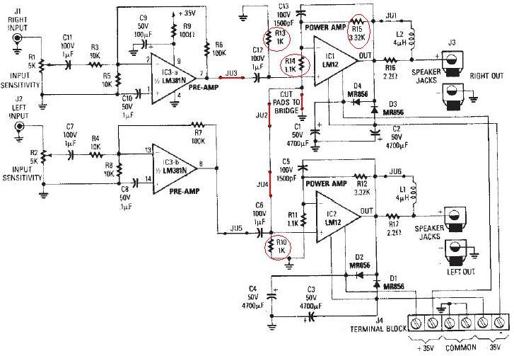
The LM12 audio amplifier circuit is designed to deliver high output power for loads with impedances of 4 ohms or 8 ohms. The maximum output power achievable by this amplifier is approximately 60 watts for a 4-ohm load and...