
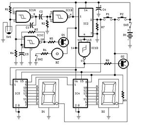
Symmetrical division circuit diagram
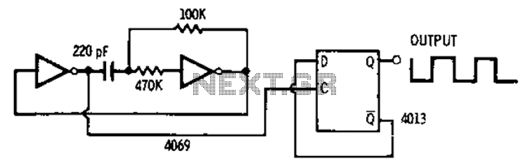
The 4013 integrated circuit contains two D-type flip-flops that can be configured to operate in an astable multivibrator mode. In this configuration, the flip-flops continuously toggle between high and low states, producing a square wave output. This square wave signal serves as a clock pulse for various digital circuits and applications.
The astable multivibrator setup involves connecting the output of one flip-flop to the clock input of the other. This arrangement effectively divides the input frequency by two, allowing the circuit to produce an output frequency that is half of the input frequency. The symmetrical nature of the output ensures that the high and low states are equal in duration, resulting in a duty cycle of 50%.
To achieve the desired frequency, external resistors and capacitors are connected to the flip-flops, determining the timing characteristics of the oscillation. The frequency of oscillation can be calculated using the formula:
\[ f = \frac{1}{2 \times R \times C} \]
where \( R \) represents the resistance and \( C \) represents the capacitance in the timing network. By adjusting these components, the output frequency can be fine-tuned for specific applications.
The 4013 D-type flip-flops are suitable for various digital applications, including frequency dividers, pulse generators, and clock signal generation. Their versatility and reliability make them a valuable component in digital circuit design.4013 pairs of D-type flip-flop in the astable multivibrator is used as a binary divider output, will produce the output frequency of the multivibrator frequency symmetrical hal f 50/50.
Related Circuits
The bi-directional sequencer employs a 4-bit binary up/down counter (CD4516) and two "1 of 8 line decoders" (74HC138 or 74HCT138) to create the well-known "Night Rider" display. A Schmitt Trigger oscillator generates the clock signal for the counter, with...
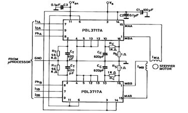
The diagram below illustrates a Two Phase Bipolar Stepper Motor Driver utilizing the PBL3717A. It depicts two PBL3717A integrated circuits (ICs) that control and drive two bipolar stepper motors. The Two Phase Bipolar Stepper Motor Driver circuit is designed to...
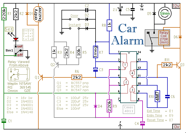
This car alarm circuit includes exit and entry delays, an instant alarm zone, an intermittent siren output, and automatic reset. By incorporating external relays, it is possible to immobilize the vehicle and activate the flashing lights. The car alarm circuit...
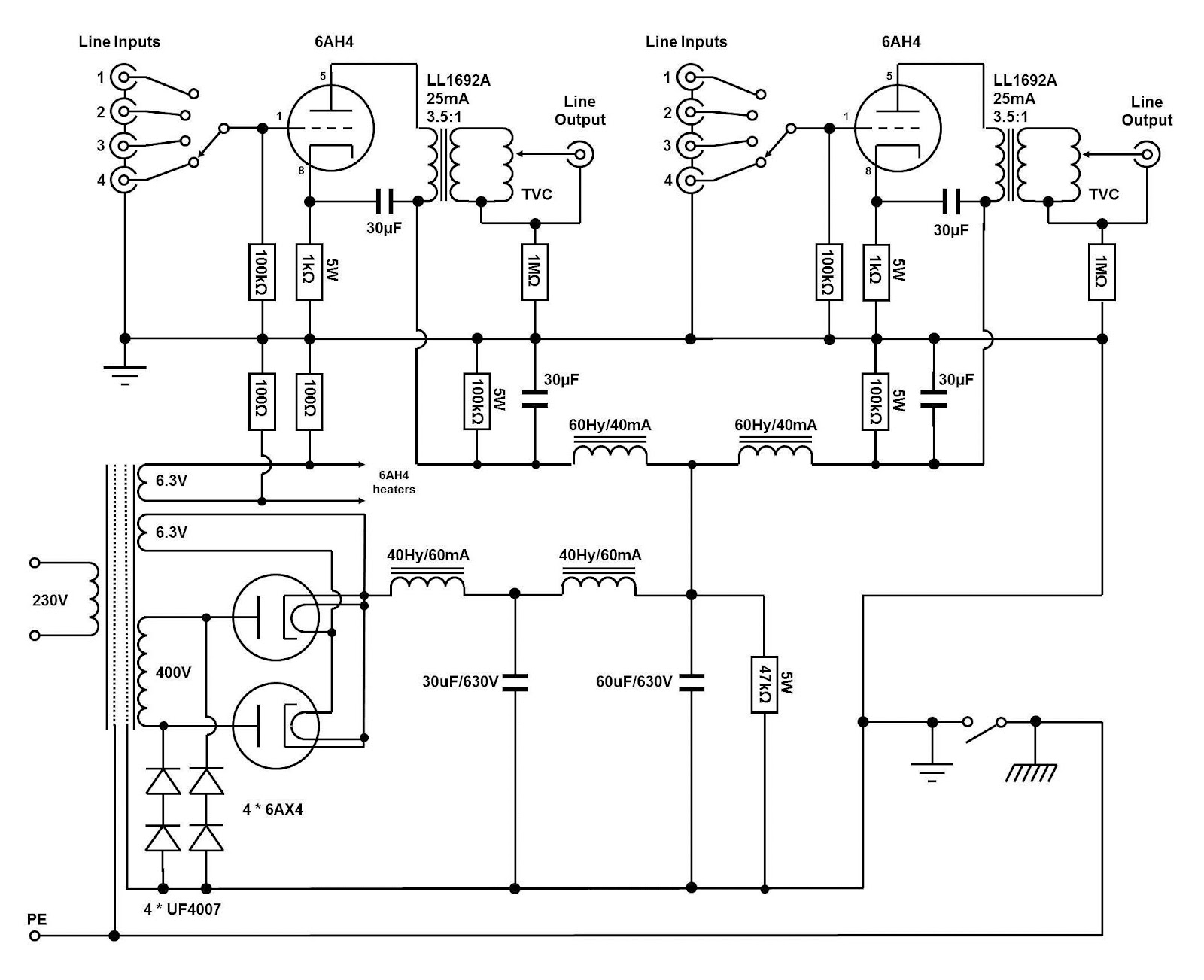
The circuit and assembly process of the line stage is presented in two separate articles. This linestage shares the same circuit as the two chassis version previously described. However, in this design, the power supply and preamplifier are housed...
The two drawings utilize the LM324 operational amplifier to create a low-voltage comparator. Resistor R1 is part of a voltage divider circuit, while operational amplifier A1 is configured to a reference voltage level U1. Resistor R2 forms another voltage...
This custom mod gives your computer the personality of KITT, the computerized car from Knight Rider TV fame. The project is a light display which imitates the dot in KITT's hood. It looks like the scanning eye of the...