
Two Phase Bipolar Stepper Motor Driver Circuit using PBL3717A

The Two Phase Bipolar Stepper Motor Driver circuit is designed to efficiently control the operation of bipolar stepper motors, which are commonly used in various applications requiring precise positioning and motion control. The PBL3717A IC is specifically engineered for driving bipolar stepper motors, providing the necessary control signals and power management features.
In this configuration, each PBL3717A IC is responsible for one phase of the stepper motor, allowing for coordinated movement. The circuit typically includes input terminals for receiving control signals, which dictate the stepping sequence and speed of the motors. The output terminals are connected to the motor windings, enabling the current flow necessary for motor operation.
The schematic may also incorporate additional components such as resistors, capacitors, and diodes for signal conditioning, noise filtering, and protection against voltage spikes. Proper selection of these components is crucial to ensure reliable operation and to enhance the performance of the stepper motor driver.
The PBL3717A ICs are capable of handling significant current levels, making them suitable for driving larger stepper motors. The circuit design should ensure adequate heat dissipation, especially when operating at high currents for extended periods. Heat sinks or active cooling methods may be employed to maintain optimal operating temperatures.
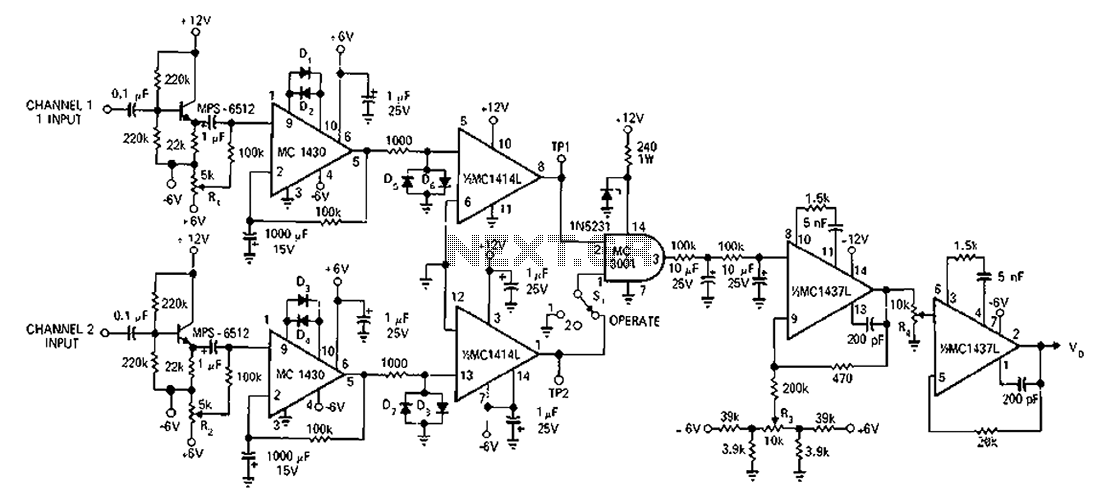
This driver configuration allows for microstepping capabilities, which can improve the resolution and smoothness of motor movements. By varying the current through the motor phases in a controlled manner, finer control over the motor's position can be achieved, making this schematic ideal for applications in robotics, CNC machines, and other precision motion systems.The diagram below schemes Two Phase Bipolar Stepper Motor Driver using PBL3717A. It shows two PBL3717A IC that control and drive two bipolar stepper motor 🔗 External reference
Related Circuits
This sound-controlled lighting circuit design is utilized to adjust the brightness of connected lights in synchronization with captured sound. The sound-controlled lighting circuit operates by detecting audio signals through a microphone or sound sensor. The circuit typically consists of several...
MP3 players are very popular today, especially the smaller memory-stick formats that are easy to transport, allowing for personal sound systems on the go. However, when sharing music with others, these players often lack sufficient power. The MP3 booster...
A circuit designed to operate within a frequency range with an accuracy greater than 2% for generating Bode plots. It converts two sine waves into a square wave, taking into account the overlap relative to the total input wave...
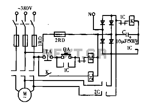
A DC motor is depicted in a dynamic braking circuit. When the stop button (SB2) is pressed, the contactor (KM1) is deactivated, causing its movable contact to disconnect, which interrupts the electrical voltage. Additionally, relay (KV) is activated, closing...
This is a single alarm circuit. The circuit includes automatic exit and entry delays, a timed bell cut-off, and a system reset. It has provisions for normally open and normally closed inputs. The single alarm circuit is designed to provide...
The function of the sound level display circuit is to enhance the appearance of an amplifier circuit or a radio player. It provides an impressive visual representation of audio levels. The sound level display circuit serves as a visual indicator...