
16 Stage Bi-Directional LED Sequencer circuit
The bi-directional sequencer circuit is designed to produce a visually appealing LED display, reminiscent of the "Knight Rider" effect, where lights sequentially illuminate in a back-and-forth motion. The core of this circuit is the CD4516, a 4-bit binary up/down counter that can count both upwards and downwards based on the control signals provided. The counting direction is determined by the ET/RESET latch, which is implemented using Schmitt Trigger inverters (74HC14). This choice of components is essential as the 74HC14 has a higher input trigger level, ensuring reliable operation in CMOS applications.
The clock signal that drives the counter is generated by a Schmitt Trigger oscillator, which provides a stable and adjustable frequency. The inclusion of a 500K potentiometer allows for fine-tuning of the oscillation rate, enabling the user to customize the speed of the LED sequence. The output of the counter is fed into two 1 of 8 line decoders (74HC138 or 74HCT138), which interpret the binary count and activate the corresponding output lines, driving the LED display.
The design includes a mechanism to reverse the counting direction upon reaching the maximum or minimum count. When the counter reaches its maximum value (1111), the low output from pin 7 of the CD4516 triggers the latch to switch the counting direction to decrementing. Conversely, when the counter reaches the minimum value (0000), the latch resets, allowing the counter to increment again on the next clock pulse. This cyclic behavior creates the characteristic "running light" effect.
For applications requiring higher voltage loads, such as 12-volt/25-watt lamps, the circuit is designed to interface with these loads using transistors. Each lamp is connected to the output of the decoders through a pair of transistors, allowing the low-voltage CMOS logic to control higher voltage devices safely and effectively. This design consideration ensures that the circuit can be used in a variety of practical applications, from decorative lighting to functional indicators.The bi-directional sequencer uses a 4 bit binary up/down counter (CD4516) and two "1 of 8 line decoders" (74HC138 or 74HCT138) to generate the popular "Night Rider" display. A Schmitt Trigger oscillator provides the clock signal for the counter and the rate can be adjusted with the 500K pot.
Two additional Schmitt Trigger inverters are used as a S ET/RESET latch to control the counting direction (up or down). Be sure to use the 74HC14 and not the 74HCT14, the 74HCT14 may not work due to the low TTL input trigger level. When the highest count is reached (1111) the low output at pin 7 sets the latch so that the UP/DOWN input to the counter goes low and causes the counter to begin decrementing.
When the lowest count is reached (0000) the latch is reset (high) so that the counter will begin incrementing on the next rising clock edge. The three lowest counter bits (Q0, Q1, Q2) are connected to both decoders in parallel and the highest bit Q3 is used to select the appropriate decoder.
The circuit can be used to drive 12 volt/25 watt lamps with the addition of two transistors per lamp as shown below in the section below titled "Interfacing 5 volt CMOS to 12 volt loads" 🔗 External reference
Related Circuits
An integrated circuit is precisely that: an integrated circuit. These small packages combine numerous individual components to perform a specific function. They vary in shape and size depending on their complexity. They are categorized into functions such as audio,...
This device is designed to be a simple, inexpensive comparator intended for use in a solar cell power supply setup where a quick indication of "too low" or "just right" voltage is needed. The circuit consists of one 5V...
This type of sensor switch is ideal for creating touch-operated bells and buzzers in small toys, which function for a limited duration before automatically shutting off. The trigger's input impedance is very high, allowing the touch sensor switch to...

This is an LED VU Meter circuit using the LM3914 IC, designed to visually represent audio signals in stereo or sound applications. The circuit is straightforward to assemble, utilizing a single integrated circuit (IC) to display 10 levels of...
Are you unfamiliar with the basics of electronics? An online store has recently opened, offering four excellent books on basic electronics for sale. Reviews of these books are available, and purchases can be made as desired. These books are...
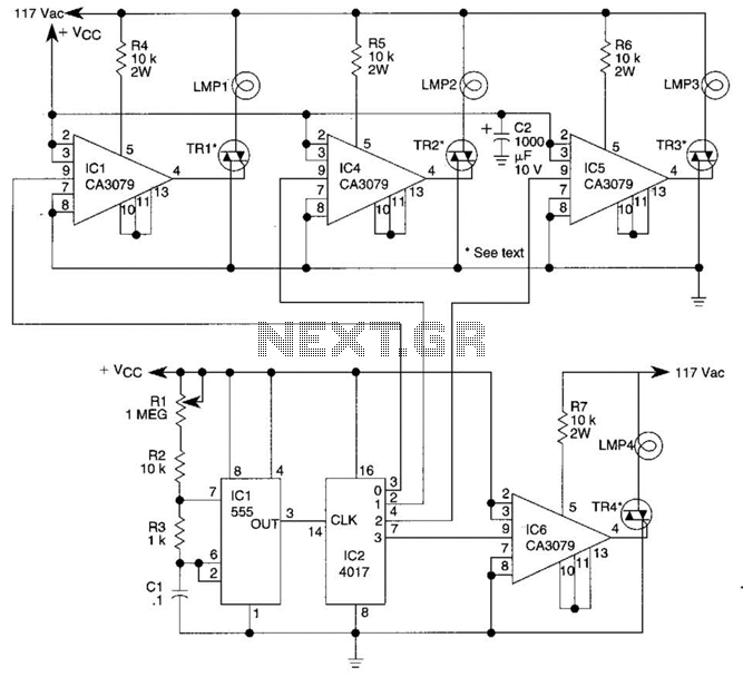
A 555 timer (IC1) controls a 4017 CMOS decade counter. The first four outputs of the 4017 drive a CA3079 zero-voltage switch. Pin 9 of the CA3079 is utilized to inhibit output from pin 4, effectively disabling the stream...