
IR Remote Control Tester
This circuit schematic consists of a few key components that facilitate its operation. The TSOP1738 IR receiver is the primary component, responsible for receiving the infrared signals emitted by the remote control. It operates at a carrier frequency of 38 kHz, which is standard for many remote control devices. The receiver amplifies and demodulates the incoming signal, outputting a square wave signal at approximately 700 Hz when it detects a valid IR signal.
The piezo buzzer, connected directly to the output of the TSOP1738, serves as the auditory indicator of the detected signal. When the IR receiver picks up a signal from the remote control, the buzzer produces a chattering noise, alerting the user to the remote's functionality.
Power supply stability is crucial for the reliable operation of the circuit. A 9V PP3 (6F22) battery is used to power the circuit, and a voltage regulator or a simple resistor divider can be implemented to ensure that a stable 5 V is provided to the TSOP1738 and the buzzer. This arrangement allows the circuit to operate efficiently without the need for complex power management.
The design is flexible, as it can accommodate different IR receiver ICs and can be adapted to work with varying carrier frequencies. However, it is important to note that while the circuit will still function with mismatched frequencies, the effective range may be reduced. This versatility makes the circuit suitable for testing a variety of remote control devices, confirming their operation through an audible output.This small circuit is ideal for checking the basic operation of an infrared remote control unit. The circuit is based on the brilliantly simple idea of connecting a piezo buzzer directly to an IR receiver IC. This method is almost as simple as connecting a photodiode directly to the input of an oscilloscope, but has the advantage that no oscillosc
ope is needed: the compact unit is always ready to use and much easier to carry around than bulky test equipment. Operation of the remote control is indicated by the buzzer making a chattering noise. The circuit is very sensitive and has a range of several meters. The TSOP1738 integrated IR receiver accepts, amplifies and demodulates the IR signal from the remote control, producing an output with a frequency of around 700 Hz.
The piezo buzzer is connected to its output, rendering the signal audible. All the other components are simply concerned with producing a stable 5 V power supply from the 9V PP3-(6F22) type battery. Instead of the TSOP1738 similar devices from other manufacturers can be used, and of course carrier frequencies other than 38 kHz can be used.
The circuit still works if there is a mismatch between the nominal carrier frequencies of the transmitter and receiver IC, but range is reduced. It is still, however, adequate for determining whether a remote control is producing an IR signal or not.
🔗 External reference
Related Circuits
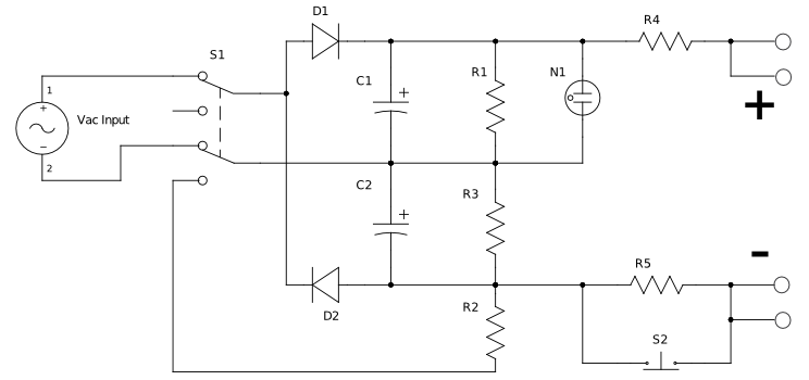
This circuit is designed for testing zener diodes. It connects to a 120V AC line and boosts the output voltage to over 300V, enabling the testing of zener diodes with various voltage ratings. The circuit features a push-button switch...
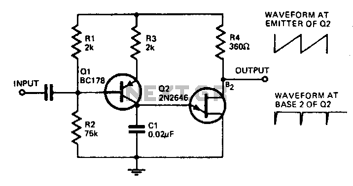
With the component values shown, the oscillator has a frequency of 8 kHz. When an input signal is applied to the base of Q1, the current flowing through Q1 is varied, thus affecting the time required to charge C1....
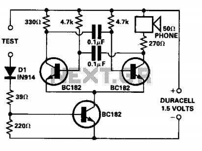
The continuity tester is designed for tracing wiring on printed circuit boards. It consumes significant power only when the test leads are shorted, eliminating the need for an On/Off switch. The voltage applied at the test terminals is not...
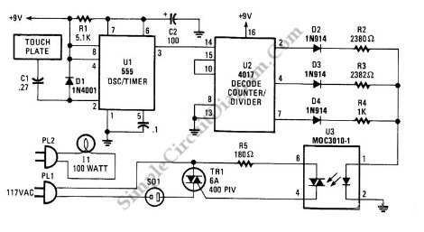
This is a three-mode lamp dimmer circuit with touch control. This circuit can be used to control a lamp in three operation modes: dim, off, and bright. It utilizes a NE555 timer. The three-mode lamp dimmer circuit designed with touch...

The 10A H-Bridge Motor Controller circuit appears straightforward, but several critical aspects should not be overlooked. The primary components utilized in the circuit include the TIP147, TIP142, and 2N2222 transistors. The power supply circuit operates at +12V, which is...
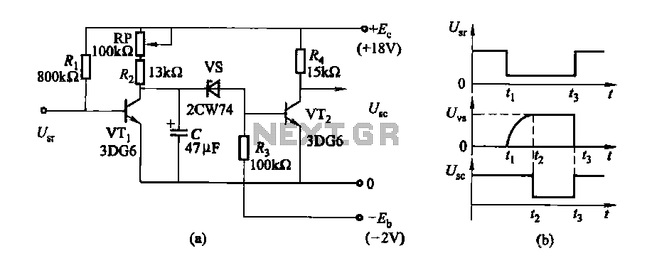
The delay time ranges from 0.5 to 3.5 seconds, which can be adjusted using the potentiometer RP to modify the delay duration. The circuit utilizes a timing mechanism that allows for the adjustment of delay intervals between 0.5 seconds and...