
T5753 T5753 UHF ASK/FSK Transmitter
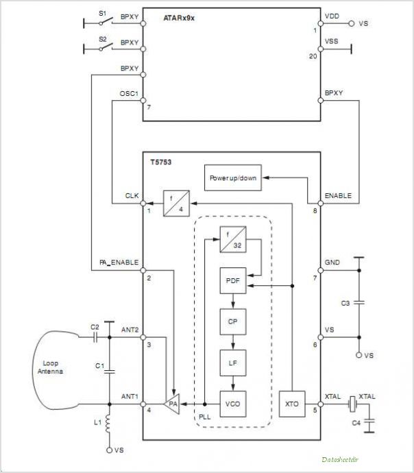
The TA0038 FSK modulator operates by utilizing a phase-locked loop architecture to achieve frequency shift keying (FSK) modulation. The modulation voltage is effectively injected into the PLL, which serves to stabilize the output frequency of the carrier synthesizer. The two methods of injection provide flexibility depending on the design requirements and sensitivity needed in the application. The first method involves combining the modulation voltage with the loop error voltage, thereby allowing for a more responsive modulation effect on the VCO tuning. The second method, which employs a separate tuning port, may be advantageous in scenarios where reduced sensitivity to voltage changes is desired, potentially enhancing stability in noisy environments.
The modulation process results in a shift in the carrier frequency corresponding to the data being transmitted. This frequency deviation is critical for the demodulation process at the receiving end, where the PLL must accurately track the carrier frequency despite the introduced modulation. However, the PLL's corrective mechanism can inadvertently filter out lower frequency components of the modulating signal. This is particularly problematic when transmitting long sequences of identical bits, as the lack of frequency variation may lead to misinterpretation of the signal, introducing errors in the received data.
In summary, the TA0038 FSK modulator is a cost-effective solution for frequency shift keying applications, but designers must be aware of the implications of PLL dynamics on signal integrity, especially in the context of varying data patterns. Proper design considerations should be taken to mitigate the effects of high-pass filtering on the modulation signal to ensure reliable communication performance.A typical, low cost, FSK Modulator TA0038 is implemented by injecting the modulation voltage into the phase lock loop of the Carrier synthesizer. This is done in two ways, by summing the modulation voltage and the loop error voltage together and applying that to a VCO tun- ing port.
Or, by using a separate tuning port usually having lower sensitiv ity to voltage changes. The modu- lating data would change the Carrier frequency by a predetermined amount (deviation). This, however, causes a frequency error within the PLL that the loop begins to correct for. The effect of the loop correcting for the frequency errors caused by the modulation is analogous to passing the modulating signal through a high pass Filter Lower frequency components of the modulation signal get filtered off (or even eliminated). This results in unreliable Communications for random data streams, especially for long strings of non-chang- ing bits.
By RF Micro Devices 🔗 External reference
Related Circuits
The operation of the circuit is managed by a microcontroller from MICROCHIP, specifically the PIC16F84. This microcontroller supports buttons and a 2-line, 16-character LCD display, along with the PLL circuit SAA1057. The voltage-controlled oscillator (VCO) is implemented using transistor...
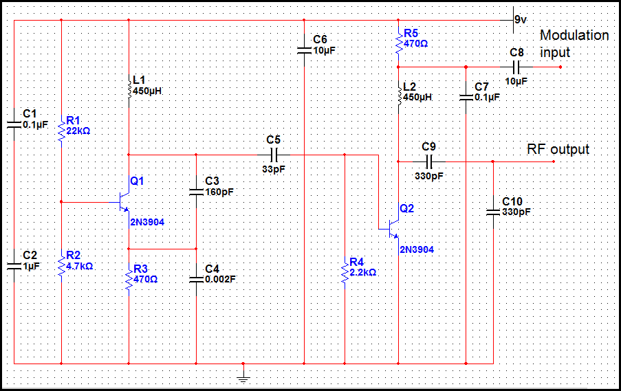
This transmitter is basic but allows the transmission of audio to an AM radio. It consists of an RF oscillator operating in the AM broadcast band, along with a modulator stage that mixes the incoming audio with the RF...
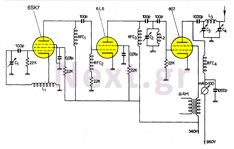
This transmitter operates in the shortwave range from 6 MHz to 22 MHz. Coil L1 serves as the shortwave oscillating coil for the 6SA7 vacuum tube and is commercially available. Capacitor C1 is a variable capacitor with a capacitance...
This UHF transmitter is designed for low power applications such as remote controls for garage doors, operating systems, and wireless alarms. This UHF FM transmitter is equipped with... This UHF transmitter operates within the Ultra High Frequency (UHF) band, which...
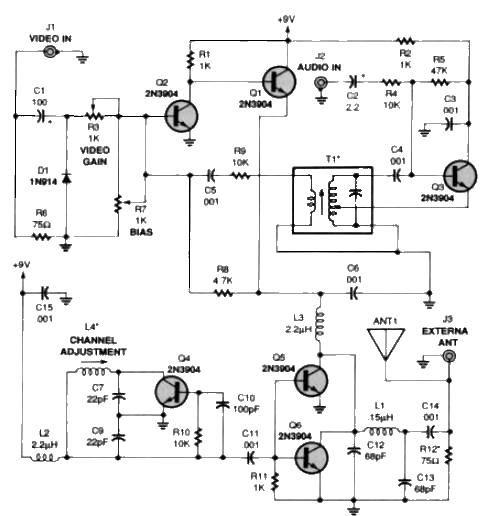
A simple TV audio-video transmitter circuit can be designed using this schematic diagram. This circuit can transmit video signals from a VCR or other devices to a TV without the need for cables. Video signals input at jack J1...
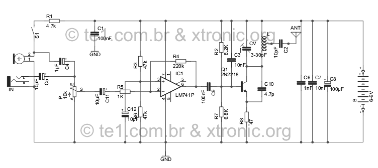
Evolution FM transmitter utilizing a 2N2218 transistor with an audio amplification stage using an LM741 operational amplifier. The design accommodates audio input from various sources such as MP3 players, MP4 devices, mobile phones, computers, and other audio sources, surpassing...