
TV audio video transmitter circuit design project
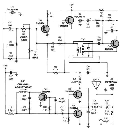
The schematic for the TV audio-video transmitter circuit consists of several key components that work together to achieve wireless transmission of audio and video signals. The input stage begins with jack J1, where video signals are received. Resistor R6 serves to terminate the input, preventing signal reflections that could degrade performance. Capacitor C1 is crucial for coupling the video signal to the clamping diode D1, which ensures that the video signal maintains appropriate amplitude levels.
The gain of the video signal is adjustable via potentiometer R3, allowing for fine-tuning of the contrast, akin to the functionality found in standard television sets. The RF transformer T1, along with its internal capacitor, forms a tank circuit that is vital for generating the Hartley oscillator's output frequency, specifically tuned to 4.5 megahertz.
The audio input is connected through jack J2, where the audio signal is coupled to the base of transistor Q3 using capacitor C2 and resistor R4. This configuration allows the audio signal to modulate the base of Q3, creating an audio subcarrier that is offset from the video carrier frequency, thereby facilitating simultaneous transmission of both audio and video.
Transistors Q1 and Q2 play a significant role in the amplitude modulation process, combining the modulated audio and video signals onto a single RF carrier signal. Coil L4's design, with its specific number of turns and the use of a ferrite slug, is critical in setting the operating frequency of the transmitter. The output stage includes transistors Q5 and Q6, which amplify the RF output from the oscillator section, ensuring sufficient signal strength for transmission.
For effective antenna matching and to filter out unwanted frequencies, capacitors C12, C13, and inductor L1 are employed. The alignment process is essential for optimal performance, requiring careful tuning of the TV receiver to an unused channel. The described procedure for tuning ensures that the transmitter operates without interference, allowing for clear reception of the transmitted signals.
The circuit's operational voltage range of 9-12V makes it versatile for various power supply configurations, while its ability to transmit signals over a distance of up to 300 feet adds to its practical utility in wireless audio-video applications. Overall, the design exemplifies a straightforward yet effective approach to constructing a wireless TV audio-video transmitter.A very simple TV audio video transmitter circuit can be designed using this schematic diagram. This TV audio video transmitter circuit can be used to transmit video signals from VCR ( or some other device ) to a TV without using any cable. Video signals input at jack J1 are first terminated by resistor R6 and coupled through capacitor C1 to clam
ping-diode D1. Potentiometer R3 is used to set the gain of the video signal; its effect is similar to that of the contrast control on a TV set. RF-transformer T1 and its internal capacitor form the tank circuit of a Hartley oscillator that`s tuned to 4.
5 megahertz. Audio signals input at J2 are coupled to the base of Q3 via C2 and R4: the audio signal modulates the base signal of Q3 to form an audio subcarrier thats 4. 5-megahertz higher than the video-carrier frequency. Transistors Q1 and Q2 amplitude modulate the video and audio signals onto an RF-carrier signal. The operating frequency is set by coil L4, which is 3. 5 turns of 24- gauge enameled wire on a form containing a standard ferrite slug. The RF output from the oscillator (L4, C7 and C9 ) section is amplified by Q5 and Q6, whose supply voltage comes from the modulator.
Antenna matching and low-pass filtering is performed by C12, C13, and L1. To align this audio video transmitter you need to tune a TV receiver to an unused channel between 2 and 6. The TV must have an indoor antenna connected directly to it; an outdoor antenna or cable won`t work. Make sure both potentiometers (R3, R7) are in middle position and apply power to the transmitter. Adjust L4 with a nonmetallic tool until the TV screen goes blank, then fine-adjust L4 for the "most-blank" picture.
After that you should see a picture on the TV screen: if you do, readjust L4 for the best picture; if you don`t, check the board for any bad connections. Next, adjust R3 for the best picture brightness and R7 for the best overall picture. The TV transmitter combines line level audio and video signals, and transmits the resulting signal up to 300 feet.
The circuit can be powered from a 9-12V power supply circuit. 🔗 External reference
Related Circuits
This simple flashing light circuit operates at 6 volts and 0.5A, exhibiting low current consumption when the light bulb is turned off. The frequency of the flashing is predetermined. The circuit consists of a power supply, typically a battery or...
This circuit features a portable solid-state bright light utilizing the LT1932 integrated circuit. It can be powered by two AA dry or rechargeable pen-light batteries. The design allows for customization of the housing, enabling various applications such as a...
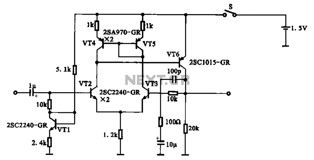
A 1.5V-powered microphone signal amplifying circuit is designed with a power supply for the microphone signal amplification. The circuit primarily consists of a differential amplifier formed by transistors VT2 and VT3. Additionally, VT6 functions as a common emitter voltage...

The robot was controlled using a Motorola 68HC11 on a special MC11 input/output board provided by the Stanford Smart Product Design Lab (SPDL). The SPDL also supplied motor controller boards, each consisting of a DS3658 stepper controller, an SN754410...
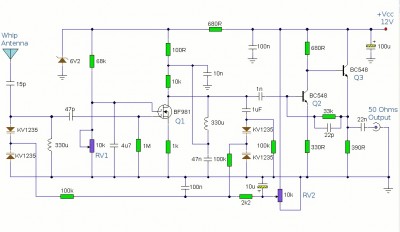
This is a booster antenna circuit designed for frequencies ranging from 550 kHz to 1650 kHz, aimed at amplifying signals received from a telescopic antenna. It covers the medium waveband within this frequency range. To drive low impedance (50...
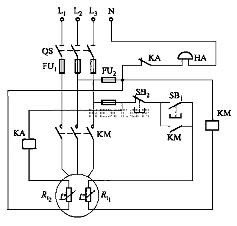
The circuit illustrated in Figure 4-2 employs two thermal resistors. One, designated as Rc, functions as overload protection, while the other, labeled Rt, serves as an alarm. The circuit in question integrates two thermal resistors to monitor temperature changes and...
Warning: include(partials/cookie-banner.php): Failed to open stream: Permission denied in /var/www/html/nextgr/view-circuit.php on line 713
Warning: include(): Failed opening 'partials/cookie-banner.php' for inclusion (include_path='.:/usr/share/php') in /var/www/html/nextgr/view-circuit.php on line 713