
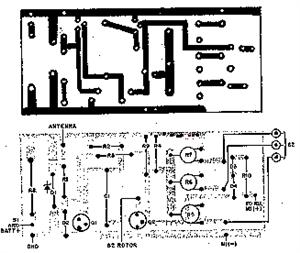
tachometer circuit diagram
The electronic circuit described is a speed measurement system that effectively utilizes a Hall effect sensor to detect rotational speed. The core of the system consists of the Hall sensor (IC1), which is positioned to sense the magnetic field generated by a small permanent magnet mounted on a turntable. As the turntable rotates, the Hall sensor generates electrical signals corresponding to the speed of rotation. These signals are processed through a series of NAND gates (notably NAND gate 3) that are controlled by a time base signal generated by IC2. This time base circuit is crucial for establishing a consistent timing reference that allows the system to accurately measure speed over a defined period.
The use of CMOS-LED components (IC4, IC5, IC6) for digital display provides a clear visual representation of the measured speed, ensuring that the results are easily interpretable. The reset and counting mechanism, facilitated by the differential reset circuit, ensures that the counting process is synchronized with the time base signal, allowing for accurate measurements in defined intervals.
The system's design emphasizes reliability and accuracy, utilizing well-established electronic components and principles. The counting process is initiated by the rise of the time base signal, and the counting circuit is designed to reset after each measurement, allowing for continuous operation without manual intervention. The update mechanism ensures that the display reflects the most recent measurements, providing real-time feedback on the speed of the rotating object. Overall, this electronic circuit represents an effective solution for speed measurement applications in various engineering and industrial contexts.It is mainly composed of permanent magnet with the disk, integrated Hall sensor, strobe gate, time base signal circuits, power counting and digital display circuit. Counting and digital display circuit using CMOS-LED digital display component CLlO2, it can count and display digital.
Dial axis of rotation input shaft connected with the measured, when measured axis, they bring along with rotating turntable. When a small permanent magnet on the turntable through the hall when the integrated sensor IC1, IC1 will speed the magnetic signals into electrical signals. The signal with the non-inverting input to gate l and the input of NAND gate 3, gate 3 with non-termination of another lost big time base circuit IC2 from a square wave pulse.
This time base signal is used to control the opening and non-gate 3 and Diao, forming strobe gate, in order to control the speed signal whether the output from the NAND gate When powered on, the speed signal was sent to NAND gate 3 input, if the time base signal is low at this time, the strobe door closed, speed signal through the gating element method. When the first time base signal comes, the door was only open the gate, while the CMOS-LED digital display components IC4, IC5, IC6 of the LE side was hosting state.
The base signal also triggered by the rising edge of the door with the non-inverter consisting of 4, 5 and by R4, R5, R7, C3, VD2 and VD3 differential reset circuit comprising, after the reset pulse output from the VD3 increased to IC4, IC5, IC6 of the R side to make the address counter reset. After the completion of the function, time base signal in a unit time (for example, lmin) remain high.
During this time, non-gated doors and door 3 has been turned on, the speed signal is sent through the gated door LED digital display components, to achieve a count in unit time. The end of the unit of time, time base signal back to low, then the door closed and gated counting circuit automatically set for the election LE end-state.
At this point, the counter content sent to the register and also displays its contents. When the second time base signal arrives, the contents of the counter is cleared again, and repeat the process. But this time the contents of the register and display the same, only when the end of the second sample, is updated and shows the new test results.
🔗 External reference
Related Circuits
During rainy seasons, it can be quite bothersome when the car wipers operate continuously without pause. Have you ever considered implementing speed control for the wipers? While there are wiper control modules available commercially, many of them can be...
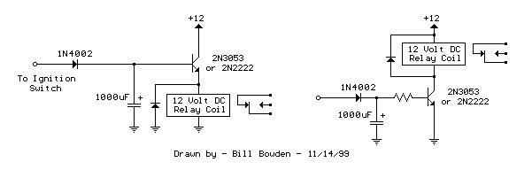
The two circuits demonstrate the process of opening a relay contact shortly after the ignition or light switch is turned off. The capacitor is charged, and the relay remains closed until the voltage at the diode anode reaches +12...
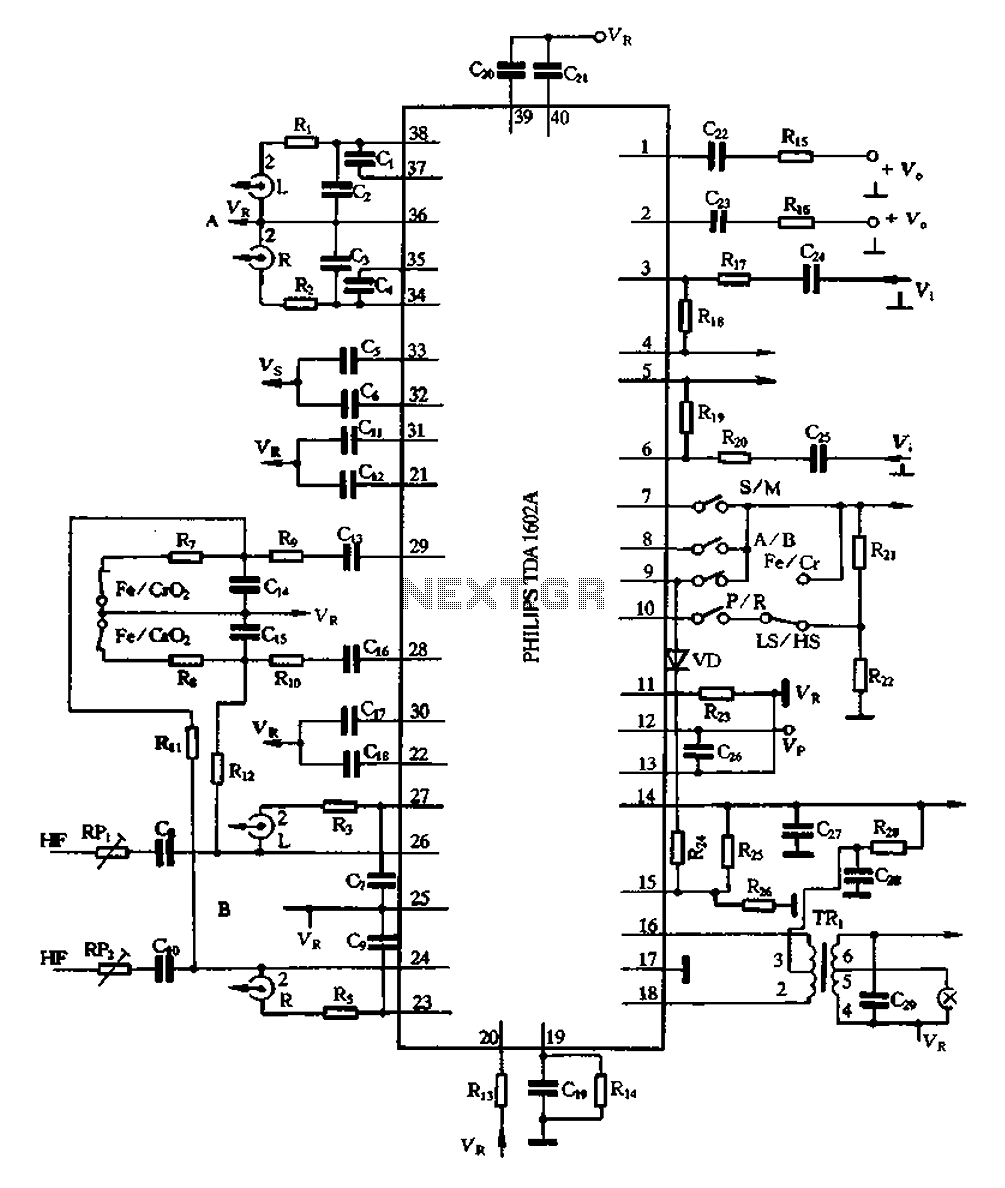
The A1602A is a 40-pin dual in-line package that functions as a playback preamplifier. It utilizes linear low-noise amplifiers with a voltage gain of 26.4 dB. Each channel has a separate discharge sound preamplifier, selected by an electronic switch...
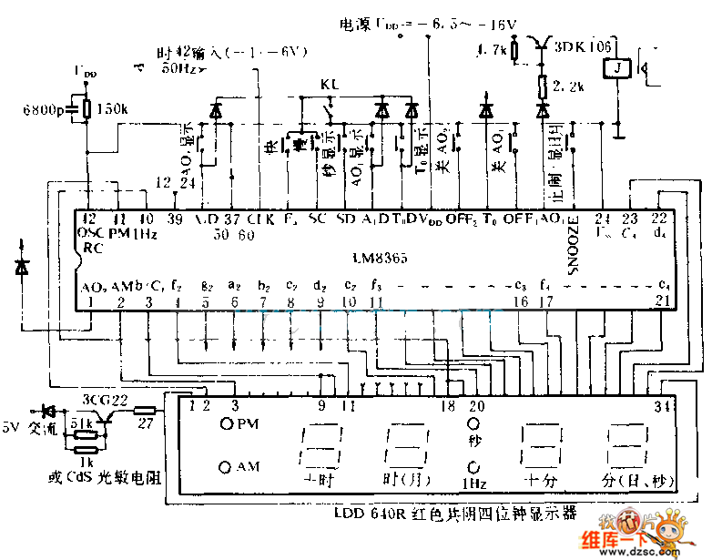
This electronic clock comprises the LM8365 and the LDD640R displays. The LM8365 can show the hour/minute and month/day. Users can set two alarm outputs, AD1 and AD2, by pressing either the 12h or 24h button. The operating voltage range...
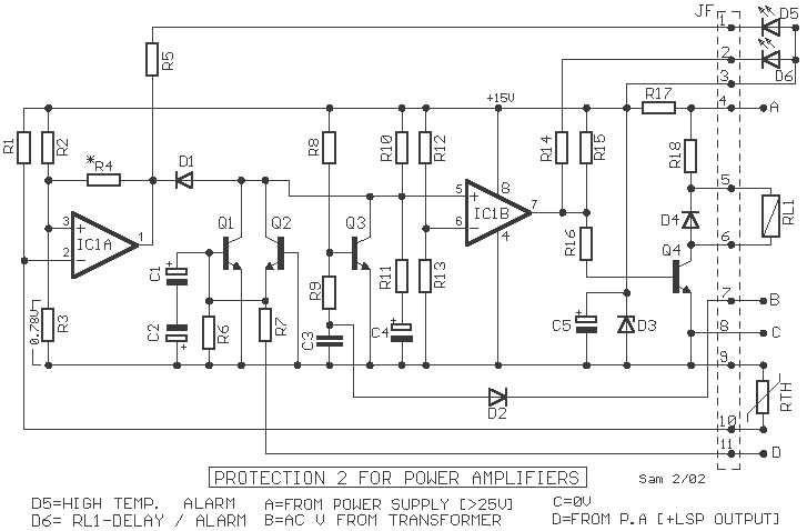
The protection circuit output amplifiers and speakers has some interesting features such as isolating the speaker from the amplifier output when shown a continuous trend in output or when the temperature gets too much cooler while providing a time...
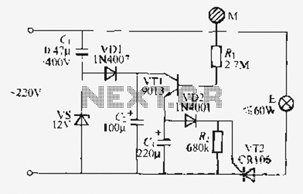
Utilize the call sheet to touch the electrical threshold M, which causes the E lamp to light up. When the same interval subparagraph is triggered, the lights will automatically turn off. A voltage regulator rectifier circuit is formed using...