
Touch light switch delay circuit
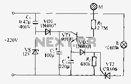
The circuit operates as a touch-sensitive light switch, utilizing a combination of capacitive sensing and thyristor control. The primary components include the touch electrode, the triode thyristor VT1, and the crystal thyristor VT2. The touch electrode serves as a sensor that detects human presence, allowing for the activation of the circuit.
When a user touches the electrode, a small alternating current is conducted through the sensor, which triggers the base of VT1. This action turns on VT1, allowing current to flow through the circuit and subsequently triggering VT2. As a result, the E lamp lights up. The design incorporates a capacitive drop voltage regulator circuit to ensure stable operation and prevent voltage spikes that could damage the components.
The discharge behavior of the circuit is also critical to its operation. When the user removes their hand from the electrode, the circuit maintains a residual charge that allows VT2 to remain conductive momentarily, thus keeping the lamp illuminated. The duration of the illumination is determined by the capacitance of Ci and the resistance of R. The larger the capacitance and the smaller the resistance, the longer the light will stay on. Conversely, decreasing the capacitance or increasing the resistance will lead to a shorter illumination period.
Design considerations include ensuring that the resistance value is not excessively high, as this could prevent VT2 from turning off properly. The circuit employs the CRiOli, 2N656J thyristor, which is capable of handling the required current and voltage levels. Overall, the design is straightforward and effective for creating a touch-sensitive lighting control system.Just use the call sheet to touch the electrical threshold M, namely E lamp lights when asked the same interval subparagraph, lights automatically turn off. VD], vs, (., C, to form a lH capacity drop voltage regulator rectifier circuit, (1 at both ends to lose thirty i V left the business flow ^} U pressure triode thyristor VT1 and product composition WI2 delay touch the switch usually, VT1 place in the off state, VL) 2 no trigger voltage output, crystal thyristor VT2 off, the lamp is not lit when E manpower touch. touch electrode films, alternating current flowing through the sensor body care injection - diode VT1 base make VT1 conduction, VIJ2 lose j n H current to trigger VT2 opened, followed by lighting the lamp E, at the same time (through VT1 Ying-speed charging.
when manpower away from the electrode sheet M, f. still bears VD2 l, doors shake _T2 discharge iU so they can maintain VT2 conduction, so that the lamp continues to emit light. when the (r basic charge is bled off in the AC H 0:00, V T2 shut off lights E was extinguished, bright electric lights the length of time, depending on the main playing Ci and R: numerical value of larger, more lighting time.
long; J beans is a short illustrated using old data, just ask about the extension of Trent 9 (is if you want to delay pregnancy. called among the most light to increase C, capacity; the contrary, can be reduced (or R value 1. It should be noted, R, the resistance can not be too large, otherwise thyristor tube VT2 7 should be easy to turn off .VT2 CRiOli, 2N656j trigger current type and other smaller sentenced Guo Jing-way thyristor (O.
S-iA / 40 (1V), the other component parameters Figure no special requirements.
Related Circuits
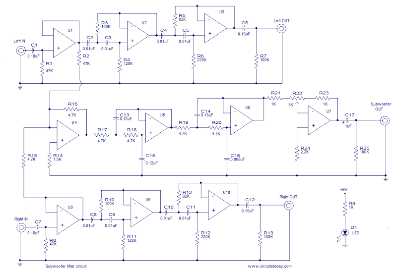
This is the schematic diagram of an operational amplifier (op-amp) based subwoofer filter. Audio frequencies below 200 Hz are typically categorized within the subwoofer range, indicating that a subwoofer filter should have a cutoff frequency around 200 Hz. The...
A simple and cost-effective TV antenna amplifier circuit is constructed using the BF961, a dual-gate N-channel MOSFET, which serves as the input and mixer stages. The described TV antenna amplifier circuit utilizes the BF961 dual-gate N-channel MOSFET due to its...
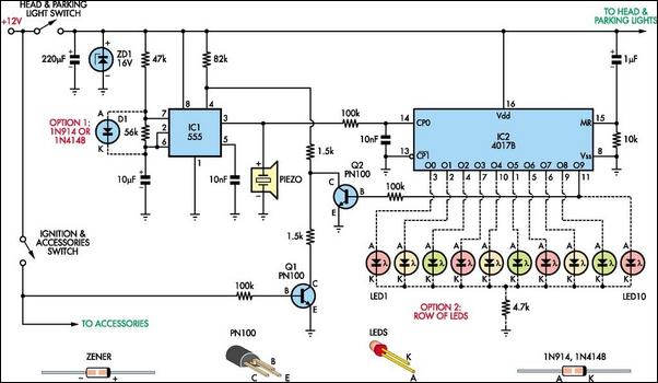
Do you drive an older car without an automatic "lights-on" warning circuit? If so, you have probably accidentally left the lights on and drained the battery on one or more occasions. This headlights reminder circuit will prevent that. It...
Convert a used CFL into a power-saving LED lamp circuit that consumes only 50mA. This gadget can be used in applications like a night light, table lamp, etc. The project involves redesigning a compact fluorescent lamp (CFL) to function as...
The goal is to transmit additional information through the use of articles. If there are any issues related to article content, copyright, or other concerns, please contact us via email at [email protected] within 15 days. The content will be...
In its simplest form, a voice-over unit is just a microphone and change-over switch feeding an amplifier, the output from the microphone having priority over the amplifiers audio signal when the "push-to-talk" switch is pressed. In this circuit, a...