
TDA0161 Metal Detector
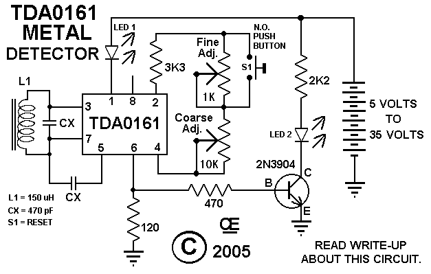
This circuit is designed to operate as a metal detector, utilizing two identical LEDs as indicators for detection status. The inclusion of a manual reset mechanism is a significant enhancement, allowing the user to reset the detection state without the interference of built-in hysteresis present in many integrated circuits. The use of standard trimpots for fine-tuning the sensitivity is crucial, with specific values of 10K and 1K recommended for optimal performance.
The circuit's operation can be summarized in a series of calibration steps that ensure effective detection. Initially, it is essential to eliminate any metallic interference near the coil to prevent false triggering. The calibration process begins by setting the fine adjustment to a midpoint, providing a baseline for sensitivity adjustments. The coarse adjustment is then employed to bring the LED to its activation threshold, indicating the circuit's readiness to detect metal.
Once the LED is activated, the fine adjustment is used to fine-tune the sensitivity to the point where the LED turns off, indicating that the circuit is not detecting any metal. It is critical to carefully adjust the fine control to the point where the LED just turns back on, as this setting represents the threshold for sensitivity. Recording this position allows for precise adjustments in future calibrations.
After noting this adjustment, a slight reduction in the setting ensures that the LED can be turned off with the manual reset, allowing for a clear indication of metal detection when the coil is activated by the presence of metal. The manual reset feature is particularly useful for conducting multiple searches without the need to recalibrate the circuit each time. By following these steps, the circuit can effectively detect metal objects in its vicinity, providing reliable performance in various applications.This particular circuit was built with an LED Indicator. There are Two LED`s Shown in the Schematic, Both do Exactly the same thing. I was just Playing with it. Advanced Schematic-2 This Modification in Advance Schematic-2 "Will Make this detector More Sensitive", by using a "Manual Reset" to help eliminate the IC`s, "Built in Hysteresis". Use Sta ndard Trimpot for the 10K and 1K Adjustments. Note: Other Coil values can Also be used, if you also use the Appropriate Values for the Trimpots and "CX" Capacitors. These are the values I used. 1) Make Sure there is NO METAL Near the Coil. 2) Set the Fine Adjustment to a "Mid Position". 3) Adjust the Course Adjustment to "Just Turn on the LED" 4) Than adjust the Fine Adjustment to Turn OFF the LED.
5) Now "Very Carefully" adjust the fine adjust to "JUST TURN the LED Back ON" and take "Careful Note of this Setting Position". 6) Now Just Back off this Setting a "TINY BIT". Pushing the "Manual Reset" Should now Turn Off the LED. Than Placing metal towards the coil will turn it back on. Pushing the Manual Reset, again turns it Off for doing another search for metal. 🔗 External reference
Related Circuits
A car battery deteriorates with use, typically lasting no more than four years. Initially, its voltage may drop to just 2V when cranking the engine. As the battery ages, its internal impedance increases, leading to a higher voltage drop...
A circuit designed to extract and measure the modulated carrier signal from an infrared (IR) remote control. This circuit does not physically separate control pulses from modulation; instead, it amplifies the complete received signal, allowing the waveform to be...

At the core of this circuit is a precision integrated temperature sensor, the LM35 (IC1), which provides a linear and directly proportional output related to temperature measurements. The LM35 temperature sensor is a well-known device used for temperature sensing applications....
This infrared detector is capable of detecting the presence of modulated infrared signals in its vicinity from various electronic sources, such as an IR handheld remote. The infrared detector operates by utilizing a photodetector that is sensitive to infrared light....
A Coil Coupled Operation Metal Detector made from readily obtainable components and using an ordinary medium receiver as a detector. The metal detector shown here may well represent a new genre. At any rate, after some exposure, it is...
The cooling is not only a PC using a small fan with an electronic commutator. A special feature of these fans is that their removal is less dependent on the load. Indicators monitoring the DC component of current may...