
IR Remote Control Modulation Detector
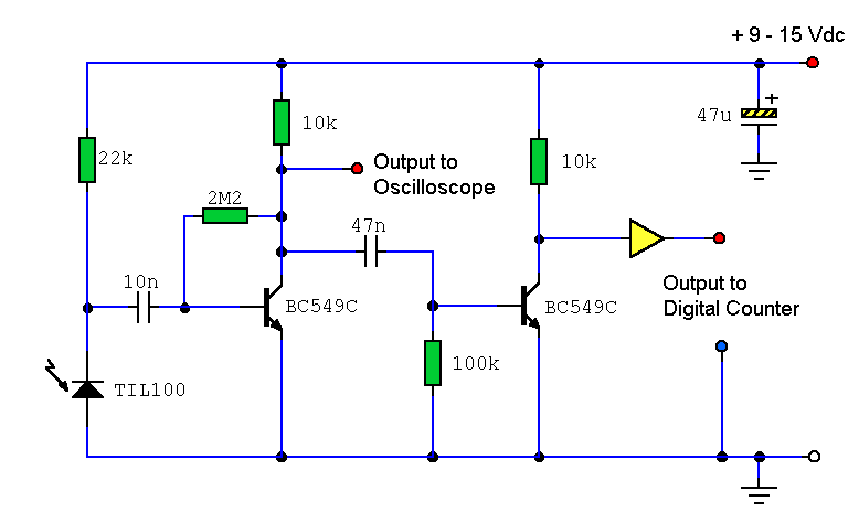
The circuit utilizes a photodiode to detect infrared signals emitted by the remote control. The TIL100 photodiode is specifically chosen for its sensitivity to infrared light and operates effectively within the circuit's design. The reverse biasing through the 22 kΩ resistor enhances the photodiode's response to incoming IR light, allowing it to generate measurable current changes.
The coupling capacitor (10 nF) plays a crucial role in blocking any DC components from ambient light while allowing the AC variations caused by the pulsed IR signals to pass through to the first amplification stage. The BC549C transistor, known for its high current gain, amplifies these small AC signals, transforming them into a more substantial voltage waveform suitable for display on an oscilloscope.
In the final amplification stage, the Class D configuration ensures that only the modulated carrier wave is amplified, effectively stripping away any DC bias. This configuration is particularly advantageous in applications requiring high efficiency and minimal distortion, as it utilizes the incoming signal as the bias source, allowing for a responsive output only when a strong IR signal is present.
The output stage, utilizing the BC549C transistor, converts the amplified analog waveform into a digital signal, facilitating easier measurement of the waveform's period. The integration of a CMOS 4050 buffer can further enhance the signal integrity, allowing for robust interfacing with frequency counters or other measurement devices.
Overall, this circuit design effectively captures and measures the modulated carrier signals from infrared remote controls, providing a valuable tool for analyzing various remote control protocols and their respective modulation characteristics.A circuit to extract and measure the modulated carrier of an Infra Red remote control. Note that the circuit does not physically separate control pulses from modulation, but amplifies the completereceived signal allowing the waveform to be displayed ideally on an oscilloscope or a frequency counter. Modulation frequencies between 1kHz and several MHz may be measured. All remote controls employing Infra Red technology use digital control signals that are modulated with a higher frequency carrier wave. The carrier wave, which is invisible to the human eye is commonly modulated between 36 and 38KHz. However, some equipment i. e. Satellite decoders may use even higher modulating frequencies. The digital control signals are relatively slow compared to the carrier frequency, typically 100 to 200 bps (bits per second).
The control pulses are sent in serial format and turn the carrier on and off. Fortunately, the control pulses of a typical remote control are long, compared to the faster modulated IR carrier wave. This very fact allows at least a few complete waveforms to be captured and measured, either on an oscilloscope or with a digital counter.
As the carrier is continually being modulated, the waveform will need to be displayed with a digital counter has a variable trigger or with an oscilloscopes manual trigger control. Light interference from nearby fluorescent light sources may also interfere with the signal, so, for this reason, I recommend to place the remote control within a few inches of the photodiode.
The detector is an IR photodiode, type TIL100. This is reverse biased via the 22k resistor and produces small changes in current when subjected to light in the IR spectrum. Ambient or steady light will produce a constant current through the photo diode, a remote control produces an alternating waveform.
The input signal is capacitively coupled to the first BC549C amplifier stage via a 10n capacitor. The capacitor will stop ambient light from passing, but not changes in light intensity. A signal of a few microamps can be passed from the photo diode into the amplifier. The high current gain of a BC549C and a medium load resistor will produce a voltage waveform that may be suitably displayed on an oscilloscope at this point. The magnitude will vary with the proximity from remote control to photo diode and also with type of remote control, hence an accurate reading is not possible.
For anyone with an oscilloscope set the volts/division control to maximum and work backwards to minimum sensitivity. The lower sensitivity of a frequency counter requires the signal to be processed further. To remove the previous amplifiers DC bias voltage, but allow only a strong modulated carrier wave to pass the last stage operates in Class D mode.
In Class D amplifiers, there are no bias components, the signal from the previous stage is used as the bias source. Therefore there will be no signal output at the collector of the rightmost BC549C under quiescent conditions, but only with a strong IR signal ( in close proximity to the photo diode).
The output transistor will be on when a positive peak arrives, and off for a negative peak. This crude method has also turned the original sinusoidal waveform into a digital one, there will be some phase shift from input to output, but the period of the waveform can still be measured. The signal can be buffered even further, if needed, the black triangle represents one gate of a CMOS 4050 buffer.
As control pulses are combined with the carrier, a frequency meter or counter is best set to measure the period of the wave, rather than the frequency. As frequency is the reciprocal of periodic time, divide 1 by the reading on the meter or counter. My own Maplin frequency counter, is shown below, displaying the result from an Aiwa Video remote control.
As can be seen (use a right click and choose your internet browsers view image) the periodic wavefor 🔗 External reference
Related Circuits
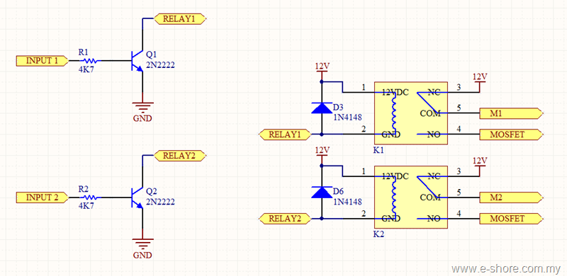
The circuit utilizes two sets of relays for each motor to switch the motor's direction, and one set of MOSFETs for each motor to control the motor's speed. The MOSFET and relay circuit will be divided into three parts...
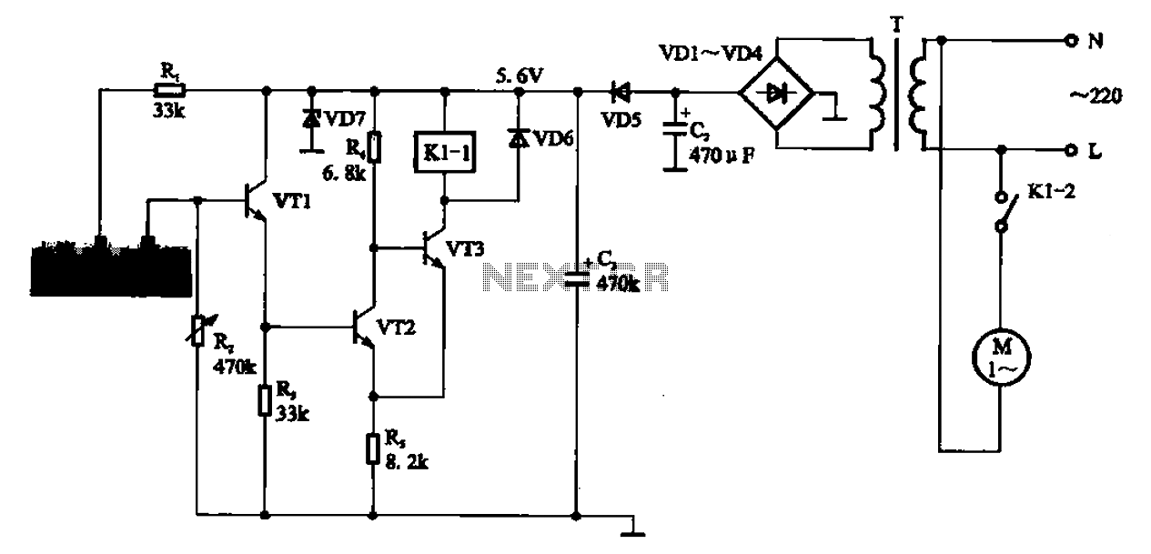
AC motor control circuit for a sprinkler. If the circuit involves an AC motor, it can be designed according to the connection shown in the figure, detailing the work process and the underlying principles of the circuit. The AC motor...
This circuit is activated by an increase in capacitance between a sensing electrode and the ground side of the line. The sensitivity can be adjusted to trigger when a human body is within inches of the insulated plate used...
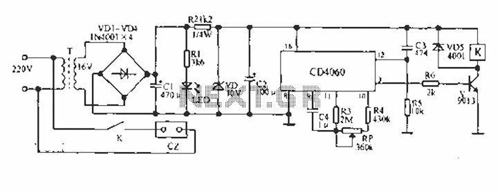
A CD4060 production time controller circuit is illustrated below. It is connected in such a way that R5 and C3 form a differential circuit to create a delay time from the start. Under the influence of the oscillating signal,...
A gas leak detector circuit that detects the leakage of LPG gas and alerts the user through audio-visual indications. The circuit operates off a 9V PP3 battery. A Zener diode is used to convert 9V into 5V DC to...
This circuit is designed to trigger on a 1 kHz tone. To change this frequency, refer to the table below, then change the resistor and capacitor values accordingly. More: all resistors are 5 or 10 percent tolerance, 1/4-watt; all...