
TDA1083 Am radio receiver circuit diagram electronic project

The TDA1083 AM radio receiver circuit is designed for optimal performance within the specified frequency range, making it suitable for various AM broadcasting applications. The choice of the TDA1083 IC is pivotal due to its integrated features, including a built-in audio amplifier that simplifies the circuit design by reducing the need for additional amplification stages. This characteristic is particularly advantageous in low-power applications where minimizing component count is crucial.
The design of the coils L1, L2, and L3 is critical for achieving the desired tuning and sensitivity. The common ferrite core for L1 and L2 enhances inductance and improves coupling between the coils, which is essential for effective signal reception. The precise number of turns for each coil is determined based on the required inductance values for optimal performance in the AM frequency range. The use of 0.2 mm copper enamel wire ensures adequate conductivity while maintaining manageable coil dimensions.
The 4.5 V DC power supply is a standard requirement for the circuit, allowing for stable operation of the TDA1083 IC. The inclusion of a 270 pF variable capacitor (C1) in parallel with L1 allows for fine-tuning of the circuit, enabling users to adjust the reception for different AM stations. This feature enhances the usability of the circuit in varying signal conditions.
Overall, this AM radio receiver circuit offers a compact and efficient solution for AM radio reception, leveraging the capabilities of the TDA1083 IC and carefully designed inductive components for reliable performance.This Am radio receiver circuit is based on the TDA1083 radio IC that can be used to build a simple MF band radio. This AM radio schematic circuit based on the TDA1083 will work in 300kHz 3MHz frequency range. This AM radio receiver circuit is very simple and require few external components. Using the TDA1083 we can make a AM FM radio receiv er but in this diagram is presented just the AM part. TDA1083 support a wide input voltage range and has a high AM sensitivity. If you don`t want much audio output power than 0. 7W you don`t need to use another audio amplifier stage to increase the audio power because the integrated circuit has a build-in audio amplifier stage. L1 and L2 needs to be placed on the same ferrite support with 10 mm diameters and 100 mm long. The L1 has 80 turns and L2 8 turns ( L2 is placed at 5 mm distance from L1 coil ). L3 has coil has 30 turns on a small piece of ferrite. For all three coils you need to use a 0. 2 mm CuEm wire. For this am radio circuit we need a 4. 5 volts dc power supply. C1 capacitor mounted in parallel with the L1 coil is a 270 pF variable capacitor. 🔗 External reference
Related Circuits
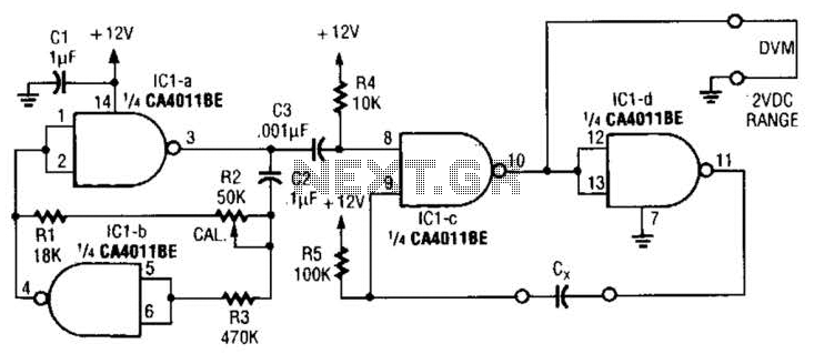
This circuit is designed for capacitor matching applications. The DC output voltage is directly related to the capacitance values of capacitor Cx. The specified circuit values are intended for capacitors in the 0.01 microfarad range; however, they can be...
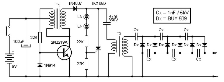
This high voltage source consists of an inverter built around a transistor that generates pulses of 150V. These pulses are supplied to an inverter made of a thyristor and a capacitor, which is connected in series with transformer T2....
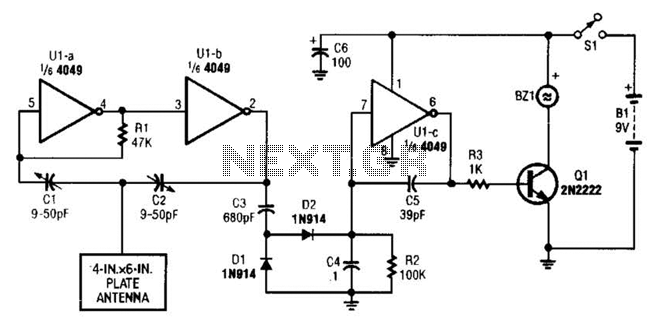
A CMOS logic gate is utilized in this circuit. When an object approaches the antenna, the change in oscillator output is detected by components 1)1 and 1)2, which is then amplified by U1C. This amplification drives Q1, activating alarm...
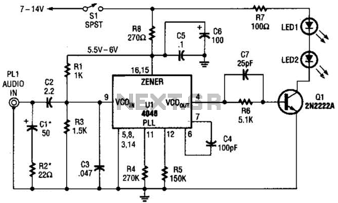
The transmitter for the wireless headphones is constructed using a CD4046 CMOS phase-locked loop, which is paired with a driver transistor and a set of infrared LEDs. While the CD4046 contains two phase comparators, a voltage-controlled oscillator (VCO), a...

This simple mock flasher LED simulates the indicator of a sophisticated alarm system. It can be placed in doors, gates, and vehicles to confuse intruders. The mock flasher LED circuit is designed to mimic the flashing behavior of a typical...
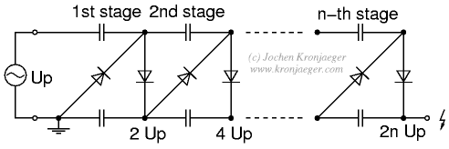
The Greinacher doubler circuit (a) transforms a grounded AC voltage (peak voltage Up) into symmetrical DC voltages of 1x Up each, thus producing 2x Up between outputs. If the input voltage is already symmetrical (e.g. as in an Obit),...