
Wireless Ir Headphone Transmitter Circuit
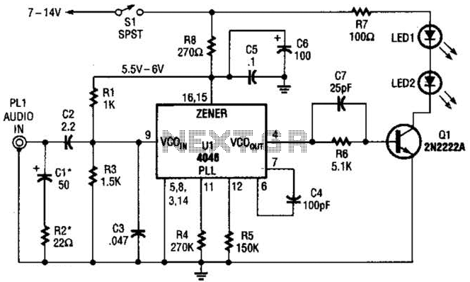
The circuit design employs the CD4046 as the central component, leveraging its VCO to generate a modulated signal that will be transmitted wirelessly. The VCO is capable of producing a frequency that varies based on the input voltage, making it suitable for audio transmission. The driver transistor serves to amplify the output from the VCO, ensuring that the signal strength is sufficient to drive the infrared LEDs effectively.
The infrared LEDs are configured to emit modulated light signals, which carry the audio information to the wireless headphones. The use of infrared technology allows for a line-of-sight communication method, minimizing interference from other electronic devices. The choice of infrared LEDs is critical, as they provide a reliable transmission medium with minimal noise.
In terms of power supply, the circuit typically requires a low-voltage DC source, which can be sourced from batteries. Proper decoupling capacitors should be included to filter out any noise that may affect the performance of the VCO and the overall circuit stability. Additionally, if the application requires, a simple low-pass filter can be implemented at the output stage to smooth the modulated signal before it reaches the infrared LEDs.
Overall, this transmitter design efficiently converts audio signals into modulated infrared light, enabling wireless audio transmission to headphones, while maintaining simplicity and reliability in its operation. The transmitter for the wireless headphones is built around a CD4046 CMOS phase-locked loop, coupled with a driver transistor, and a pair of infrared LEDs. Although the CD4046 is comprised of two phase comparators, a voltage-controlled oscillator (or VCO), a source follower, and a zencr reference, only its VCO is used in this application. 🔗 External reference
Related Circuits

This design circuit outlines a simple, low-cost, and ultra-compact VHF/UHF Low-Noise Amplifier (LNA) that can be implemented using the MAX2664 and MAX2665 devices, which are specifically tailored for VHF/UHF applications. The MAX2664 operates within the UHF frequency range of...
A buzzer circuit utilizes a PIC microcontroller to drive a piezo buzzer. The microcontroller is a low-power processor that is ideal for portable and compact devices where battery conservation is essential. The buzzer circuit employs a PIC microcontroller, which serves...

The SLB0586A integrated circuit from Siemens can be utilized to create a simple touch light dimmer circuit, allowing for the adjustment of lamp intensity. When paired with a TIC206D triac, this setup enables smooth regulation of light intensity for...
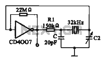
A 32 kHz clock oscillator is essential for digital circuits, as depicted in the schematic. The 32 kHz crystal clock oscillator serves to provide a time reference signal for the digital circuit. It utilizes a CMOS integrated circuit, specifically...
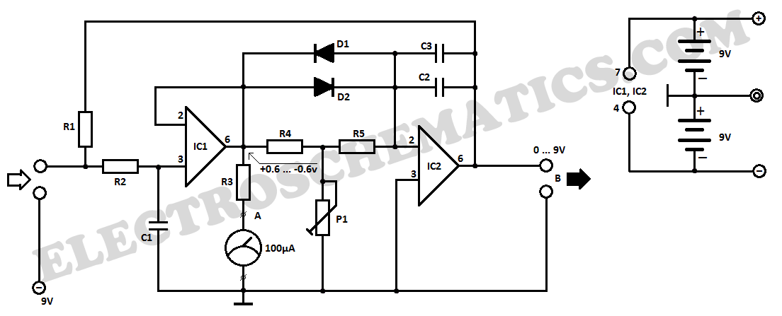
This electronic lie detector circuit project will provide two readings: one for challenging questions posed to the subject and another to indicate their emotional state. The electronic lie detector circuit operates on the principles of galvanic skin response (GSR) and...

The following circuit illustrates a Bedside Lamp Timer Circuit Diagram. This circuit is based on the CD4060 integrated circuit. Features: An LED illuminates for approximately 25 seconds. The Bedside Lamp Timer Circuit utilizes the CD4060 IC, which is a versatile...