
Electronic Metronome Circuit
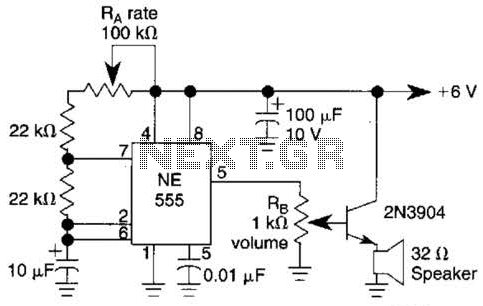
The circuit utilizes a 555 timer IC configured in astable mode to function as a low-frequency oscillator. In this configuration, the timer generates a continuous square wave output, which can be used to drive a speaker, producing sound by modulating the audio signal. The resistors Ra and Rh play crucial roles in determining the frequency and amplitude of the output waveform.
Ra, the resistor connected to the discharge pin and the threshold pin of the 555 timer, influences the rate of oscillation. By adjusting Ra, the time period of the high state of the output can be modified, thus varying the frequency of the oscillation. Rh, on the other hand, is connected to the discharge pin and ground, controlling the volume of the output signal. The combination of these two resistors allows for a customizable sound output, making it suitable for various applications such as alarms, sound effects, or simple audio applications.
The circuit is powered by a 6 V battery, providing sufficient voltage for the operation of the 555 timer and the connected speaker. The choice of a 6 V power supply ensures that the circuit remains efficient and minimizes power consumption while delivering adequate performance. To enhance the output sound, a capacitor may be connected in parallel with the speaker, which can help to smooth out the audio signal and improve the overall sound quality.
Overall, this simple yet effective circuit design demonstrates the versatility of the 555 timer in generating audio signals, with adjustable frequency and volume settings suitable for a variety of electronic projects. Ra sets the rate while RH sets the volume of clocks in the speaker. The 555 is configured as a low frequency oscillator. The circuit is powered by a 6 V battery. 🔗 External reference
Related Circuits
This is a single alarm circuit. The circuit includes automatic exit and entry delays, a timed bell cut-off, and a system reset. It has provisions for normally open and normally closed inputs. The single alarm circuit is designed to provide...
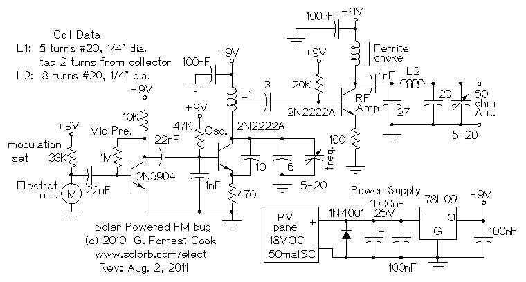
This house FM transmitter for your stereo or any other amplifier provides a strong signal strength up to a distance of 500 meters with a power output of about. This FM transmitter is designed to enhance audio transmission capabilities for...
Here are some utility circuits for use with the Ramsey FM10a, and other small FM stereo transmitter kits. This information may be helpful for setting up a micro powered FM radio station. The FM10a and similar kits tend to...

To generate and maintain the endocochlear potential (EP), perilymphatic potassium ions (K+) enter fibrocytes (F) through the Na+/K+-ATPase and Na-K-Cl cotransporter. Gap junction networks connect fibrocytes to strial basal (SB) and intermediate (SI) cells, allowing ions to enter the...
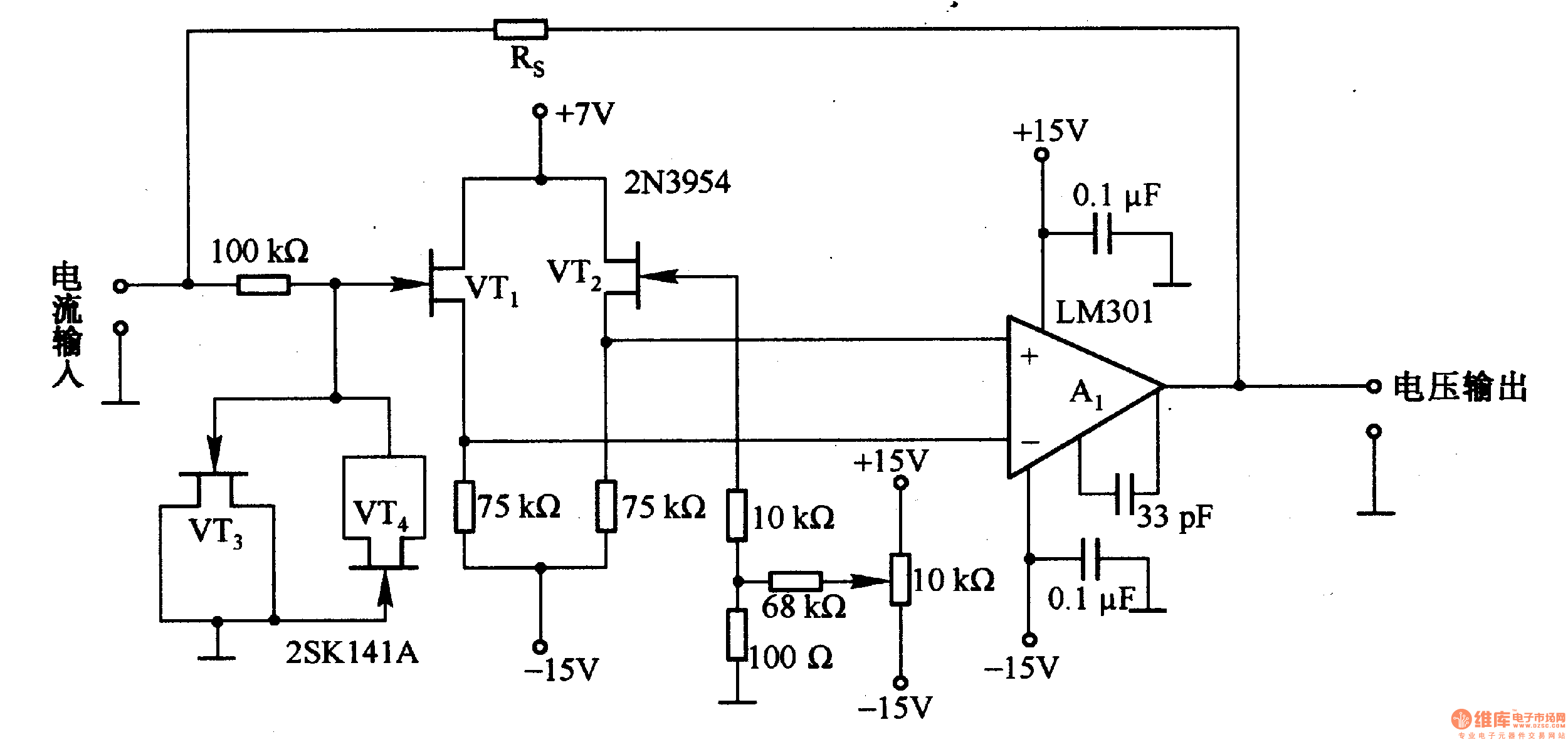
This is a low-input impedance conversion circuit with the reference resistor RS connected to the amplifier's feedback loop, resulting in an input impedance close to zero. The input current flows into the output end of the operational amplifier (Op-Amp)...
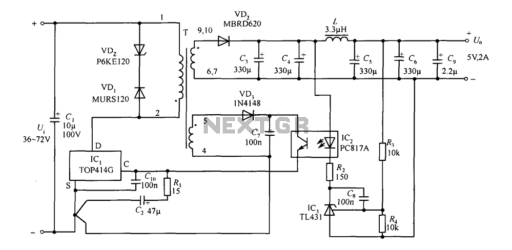
The circuit consists of a 5V TOP414G isolated switching power supply with a 2A output. C1 serves as the input filter capacitor. The circuit includes a voltage clamp protection mechanism composed of VD1. The control terminal is connected to...
Warning: include(partials/cookie-banner.php): Failed to open stream: Permission denied in /var/www/html/nextgr/view-circuit.php on line 713
Warning: include(): Failed opening 'partials/cookie-banner.php' for inclusion (include_path='.:/usr/share/php') in /var/www/html/nextgr/view-circuit.php on line 713