
85% efficiency SMPS circuit
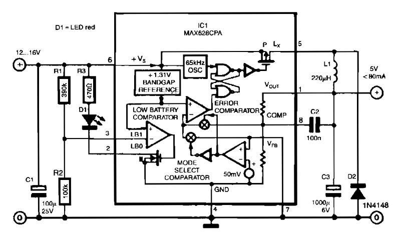
The MAX638CPA is a highly efficient CMOS step-down switching regulator that is ideal for applications requiring a stable 5V output from higher input voltages ranging from 12 to 16 VDC. This IC features an adjustable output, allowing for precise voltage control, which is essential in various electronic applications. The circuit design integrates nine external components, including inductors, capacitors, and diodes, to facilitate the step-down conversion process while maintaining efficiency.
The switching regulator operates by rapidly switching the input voltage on and off through the transistor Q1. When Q1 is turned on, the inductor stores energy, and when it is turned off, the energy is released to the output capacitor, resulting in a regulated output voltage. The high efficiency of approximately 85% ensures minimal power loss, making it suitable for battery-powered devices.
Additionally, the circuit can handle a variety of input sources, such as a 9V battery, providing a reliable 5V output with a maximum load current of 50mA. The design also incorporates a diode bridge to rectify an input alternating voltage of 12V at 800mA, ensuring that the circuit can manage different power sources effectively.
The inclusion of a digitally adjustable negative voltage output is particularly beneficial for applications such as laptop displays, where enhanced contrast is required for optimal visual performance. The overall construction of the circuit is compact, making it suitable for integration into various electronic devices.
In the context of a PC power supply, the design is straightforward, consisting of a robust metal housing that provides durability and safety. The Euro unit connector facilitates easy connection to a standard power socket, and the power switch allows for convenient operation. This combination of features makes the switching regulator circuit a versatile solution for modern electronic power management needs.The circuit is quite simple thanks to the use of MAX638CPA 5V CMOS Step Down Adjustable Switching Regulator IC. With this IC input voltage of 12 to 16 Vdc converted into direct voltage 5VDC. You can see here is only using 9 additional external components to complete the circuit. The schematic diagram come from circuit: Switch Mode Voltage Regulato r with 85% efficiency power supply. Go to that page to read the explanation about above power supply related circuit diagram. Switch Mode Power Supplies (SMPS) is now widely used in modern electronic equipment due to its compact design and high efficiency of about 80% or more. The switch-mode regulator circuit presented here has an efficiency of around 85%. The circuit. This simple switching regulator circuit have 5 V output, the input provide by a 9 V battery. It having 80% efficiency and 50mA output capability. How simple switching Regulator works: While Q1 is actually on, its collector voltage increases, delivering current.
To supply the high voltage converter suitable source of alternating voltage 12 V / 800 mA. An alternating voltage is rectified by a diode bridge with an allowable current of 1 A. Converter output voltage is adjustable between 0. . Laptop display commonly apply large screen Lcds, which generally will need a adjustable and a negative supply to ensure highest possible contrast. This circuit works with the system`s positive notebook battery supply and generates a digitally adjustable negative voltage to.
Built a PC power supply basically quite simple. It consists of a housing made of metal. A Euro unit connector is for connecting to the socket, and there is a power switch. The PC power supply has at least one. We aim to transmit more information by carrying articles. Please send us an E-mail to wanghuali@hqew. net within 15 days if we are involved in the problems of article content, copyright or other problems. We will delete it soon. 🔗 External reference
Related Circuits
S1 and S2 are normally open, push-to-close, momentary switches. The diodes can be red or green and serve solely as indicators for direction. The TIP31 transistors may need to be adjusted based on the motor specifications. It is important...
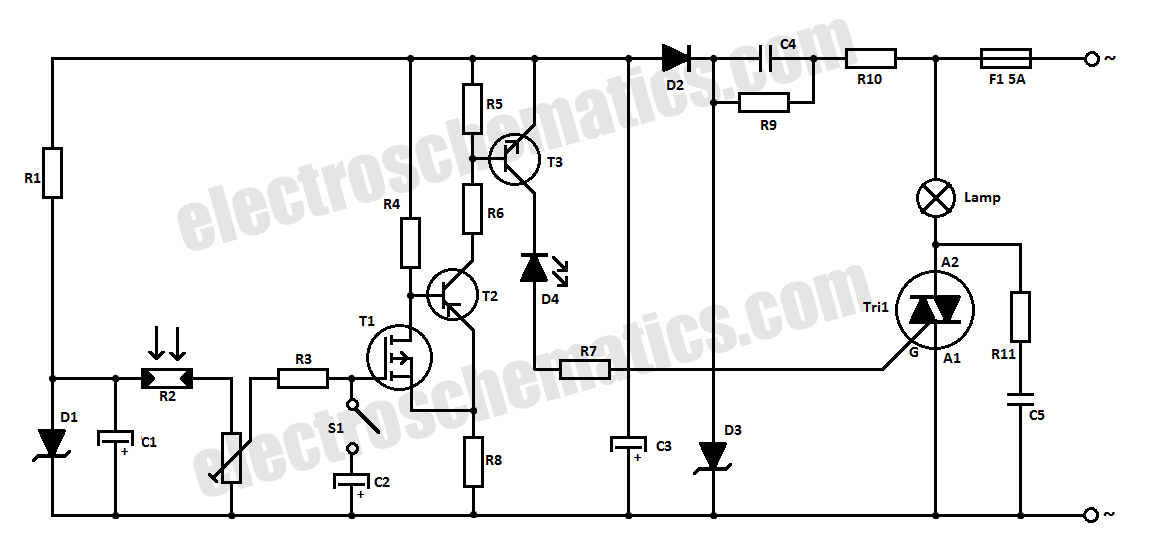
This halogen switch circuit utilizes a FET transistor, as the current is influenced by the gate voltage of the FET. The maximum gate voltage is 12V, making the circuit suitable for 12-volt lamps. The resistor R1 has a value...
This charger is based on a charging voltage of 2.4 volts per cell, in accordance with most manufacturers' recommendations. This circuit pulses the battery with 14.4 volts (6 cells x 2.4 volts per cell) at a rate of 120...
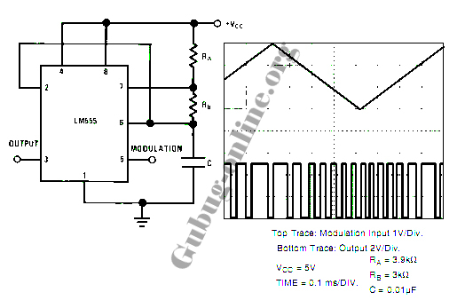
This design circuit for a pulse position modulator can be easily constructed using a 555 integrated circuit (IC). The pulse position modulator modulates the on-period while maintaining a fixed off-period. The circuit utilizes the 555 timer IC in astable mode...

To invoke the Spectrum +3 diagnostic routines, first reset the machine while holding the BREAK key down. This will bring up the test card display. Next, hold down the QAZMLP keys for a few seconds until the diagnostic title...
The EUA2032 is a high-efficiency, 2.5W mono class-D audio power amplifier. A newly developed filterless PWM modulation architecture further reduces EMI and THD+N, as well as eliminates the LC output filter, thereby reducing the external component count, system cost,...