
tda7384 class ab audio power amplifier circuit design electronic project
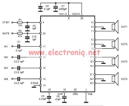
The input capacitor plays a crucial role in filtering unwanted low-frequency signals in electronic circuits. By selecting a capacitance of 0.1 µF, the circuit is designed to attenuate frequencies below 16 Hz, effectively blocking DC components and allowing only AC signals above this threshold to pass through. This is particularly important in audio applications, where low-frequency noise can interfere with signal integrity.
The cut-off frequency (fc) can be calculated using the formula:
fc = 1 / (2πRC)
where R is the resistance in ohms and C is the capacitance in farads. In scenarios where the resistance value (R) is known, the selection of a 0.1 µF capacitor will ensure that the circuit operates effectively above the specified cut-off frequency.
In practical applications, the input capacitor is typically connected in series with the signal path. This configuration allows the capacitor to block any DC offset present in the input signal while permitting the desired AC signal to reach subsequent stages of the circuit, such as amplifiers or filters.
It is also essential to consider the voltage rating of the capacitor to ensure it can withstand the applied voltage without failure. Additionally, the choice of capacitor type, whether ceramic, electrolytic, or film, can influence the performance characteristics, including frequency response and equivalent series resistance (ESR).
Overall, the input capacitor is a critical component in achieving desired frequency response and signal integrity in various electronic applications.The input capacitor is for the low frequency cut-off and the standard value for the input capacitors is 0. 1uF ( the cut-off for this value is amount to 16Hz). 🔗 External reference
Related Circuits
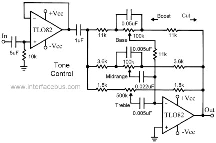
This topic continues the coverage of audio tone controls. The first entry started with a passive tone control circuit using different RC filter configurations and introduced an active filter. The second entry showed a fully designed 2-band active tone...
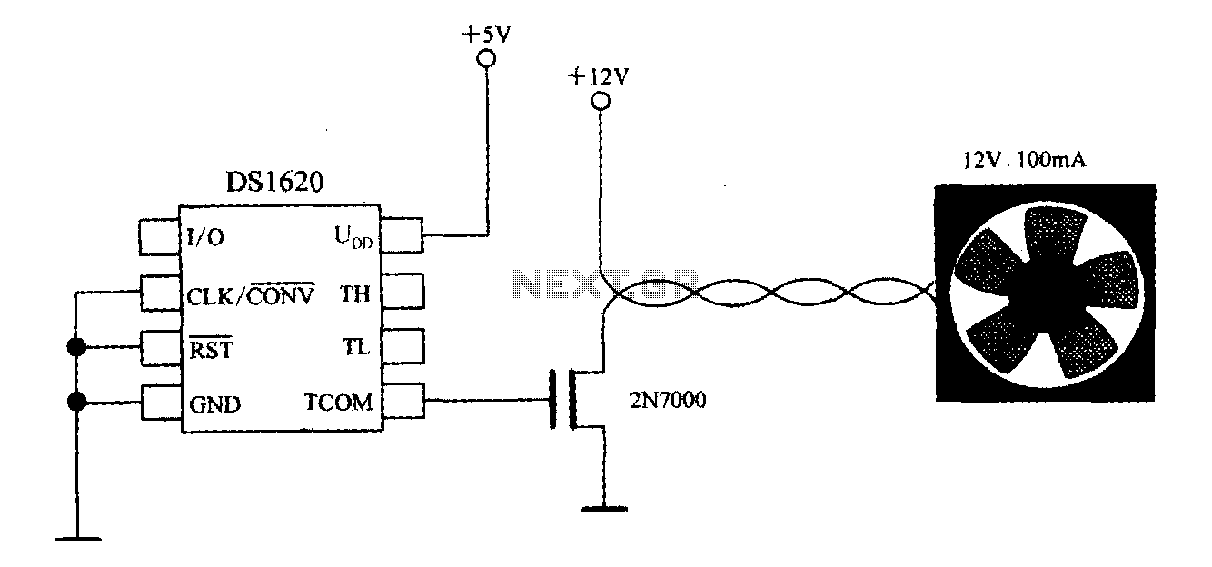
The DS1620, in conjunction with a microprocessor, is utilized to monitor temperature. By controlling the fan, the thermal conditions of the chip can be adjusted to establish a temperature control circuit as illustrated in the accompanying figure. The system...
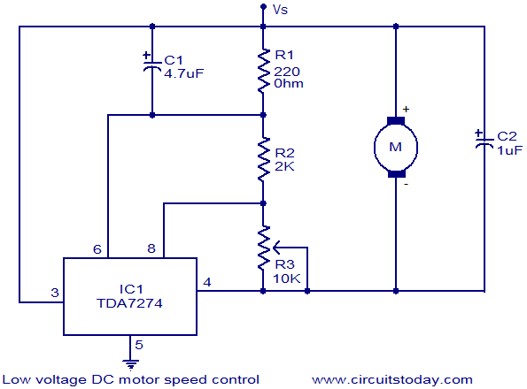
The circuit diagram illustrates a low voltage/low power DC motor speed controller utilizing the TDA 7274 integrated circuit from ST Microelectronics. The TDA 7274 is designed for low voltage and low power applications, featuring an internal voltage reference, a...
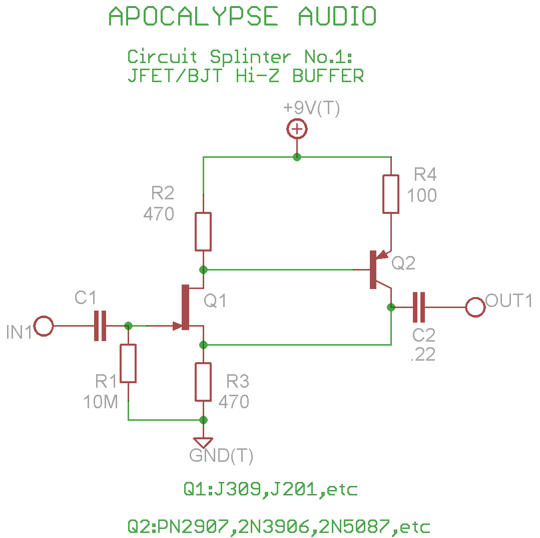
This is a common circuit often found in various resources, yet it appears to be less prevalent in stompbox applications. The circuit utilizes an NPN JFET DC coupled with a PNP BJT. The FET provides a significantly higher input...
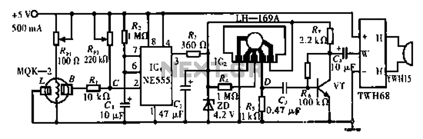
The circuit operates using the MQK-2 gas sensor, which detects the presence of combustible gases or smoke through surface adsorption. When gas is detected, the inter-electrode resistance (BL) decreases significantly. This change in resistance affects the voltage at node...
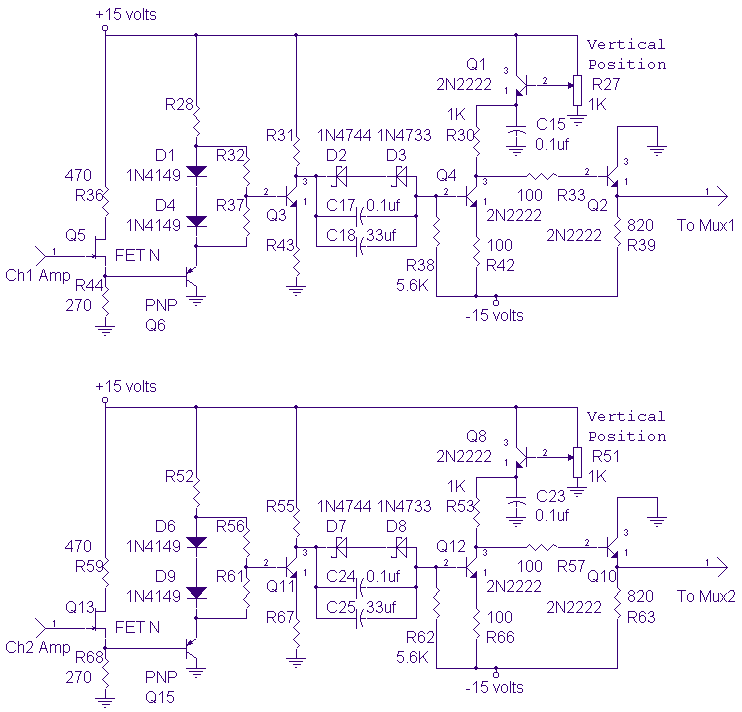
The DC-10 MHz amplifier shown below is identical for both scope channels. The input FET should be mounted directly on the adjustable attenuator switch for best frequency response. The vertical position pots, R27 and R51, change the dc level...