
Low voltage DC motor speed control circuit
The TDA7274 was primarily designed for portable music players and related devices but has since been discontinued. It is important to note that controlling the speed of a DC motor under varying load conditions can be complex. A stable voltage alone is insufficient, as the speed may decrease when a load is applied, leading to increased armature current. To maintain consistent speed, a speed regulator is necessary to adjust the motor voltage accordingly. However, excessive compensation can lead to instability in motor operation. The optimal value of R1, which determines this compensation, is critical and varies depending on the specific motor characteristics.
In contemporary applications where precise speed control is crucial, stepper motors are often preferred due to their ability to have speed determined by the frequency of applied pulses, complemented by pulse width modulation (PWM) for voltage control. This method also allows for straightforward control of the shaft position.
To implement a DC motor speed controller with adjustable speed settings (e.g., 30%, 60%, and 100% of maximum speed) using a 12V, 1A power supply transformed from 230V, a circuit design incorporating the TDA7274 can be utilized. The connection of the motor to the IC, along with the appropriate resistor and capacitor values, will facilitate effective speed control. For users unfamiliar with integrated circuit pin configurations, a pinout diagram or datasheet for the TDA7274 should be referenced to ensure proper connections are made, particularly for pins 3, 4, 5, 6, and 8.
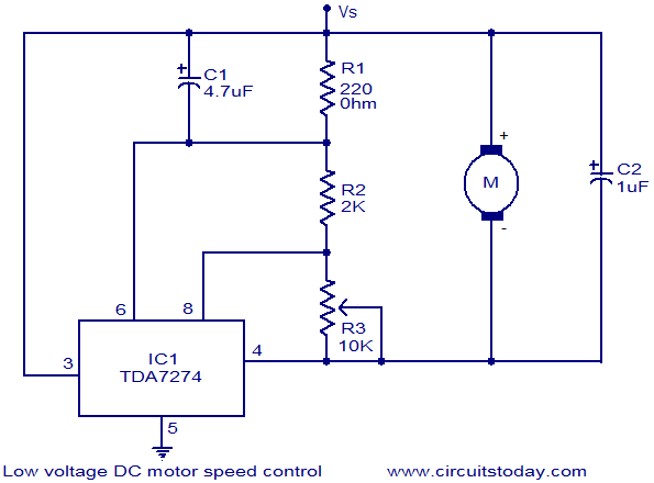
In summary, while the TDA7274 provides a foundational approach to DC motor speed control, careful consideration of component values and circuit design is essential to achieve stable and responsive motor performance in various applications.Here is the circuit diagram of a low voltage /low power DC motor speed controller based on the IC TDA 7274 from ST Microelectronics. The IC TDA 7274 is a monolithic integrated DC motor speed controller intended for low voltage/ low power applications.
Built in internal voltage reference voltage, wide input voltage range (1. 8 t0 6V), high linearity , 700mA output current, excellent temperature stability etc make this IC well suitable for almost all low power DC motor speed control applications. The motor to be controlled is connected between pin3 (Vs) and pin4 (output) of the IC. Resistor network comprising of R1, R2, and R3 is the section that deals with the speed control. Control pin (pin8) of the IC is connected to the junction of R2 and R3 and the speed of the motor varies linearly according to the position of POT R3.
Capacitor C1 rectifies the fluctuations in motor speed and capacitor C2 cancels the motor spikes. hi i am looking for a circuit that could control the following motor( with a variable resistor. i want to control the speed from zero to fairly fast. could you offer any adivice. this is the closest as i have come to an answer Thank you very much for publishing this super simple but great Circuit diagram. I already brought all the parts required. But only one problem Is. I am new in Electronics. I don`t know how how to count IC (TDA7274)pins/connectors. Which one is #3, 4, 5, 6, &8 i m looking for a circuit that can control dc motor speed and its direction of rotation and also i want to display the speed of the motor.
plz help me m really worried about my project to be submitted very soon give a circuit which would run the motor at (say ”30%, 60%, 100% )of the maximum speed of motor using only 12V, 1A supply transformed through 230V, 5A The TDA7274 was intended mainly for portable music players, and however ingenious, together with cassette players and the like, it has been discontinued and is obsolete (See manufacturers data/application sheets: ) As a general comment, though, I would like to mention that speed control of a DC motor connected to a varying load can be tricky. A stable voltage is not enough, because when a load is applied, the speed will decrease, while the armature current increases.
In order to avoid this decrease in speed, the presence of a speed regulator will increase the motor voltage enough to keep the speed virtually constant. The latter is the simplest and cheapest, and that is mainly what the TDA7274 does, or did. However, the problem here is that to much compensation will make the motor run faster, thus making the system unstable.
Moreover, this type of compensation lacks the accuracy of the negative Feedback method, and it also depends heavily on the electromechanical properties of the individual motor. In the circuit diagram, R1 determines this compensation, it`s optimal value being dependent of the motor in question.
A too big value will inevitably lead to instability. Today, in applications where speed control is essential, small motors will often be step motors, whose speed is genuinely determined by the frequency of the applied pulses, while PWM (pulse width modulation) is used for controlling the applied voltages. For a step motor, even the shaft position is easily controlled. Disk drives rely on this. 🔗 External reference
Related Circuits
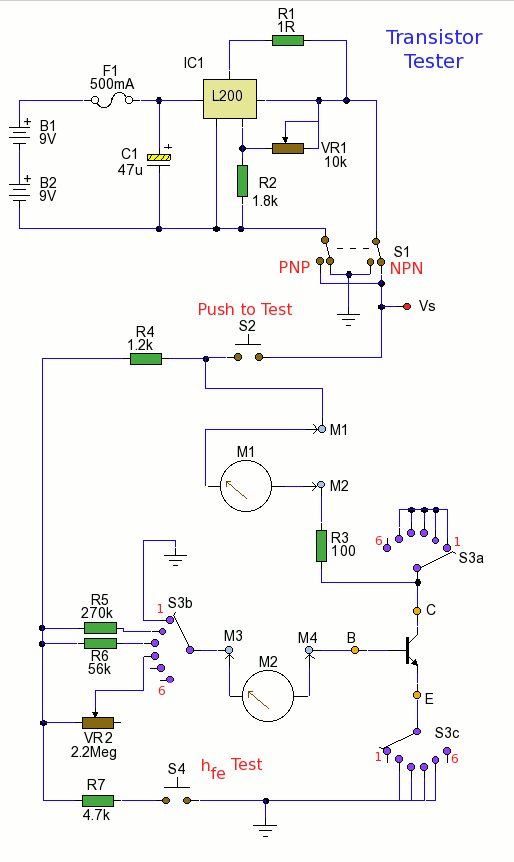
Using the tester is straightforward. Begin with the power off and insert a transistor into the test socket. Set switch S1 for either NPN or PNP configuration and rotate switch S3 to the desired test position. Adjust variable resistor...
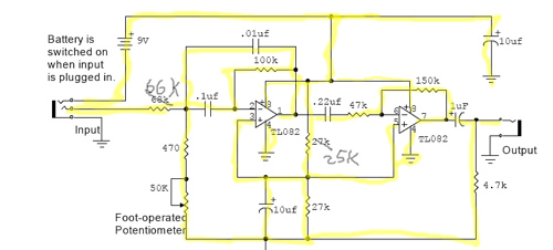
The core of this drum machine is based on an electronic drum stick. Swinging the stick produces drum sounds, specifically three sounds: snare, bass drum, and hi-hat. When the stick is swung, it plays a snare sound. There are...
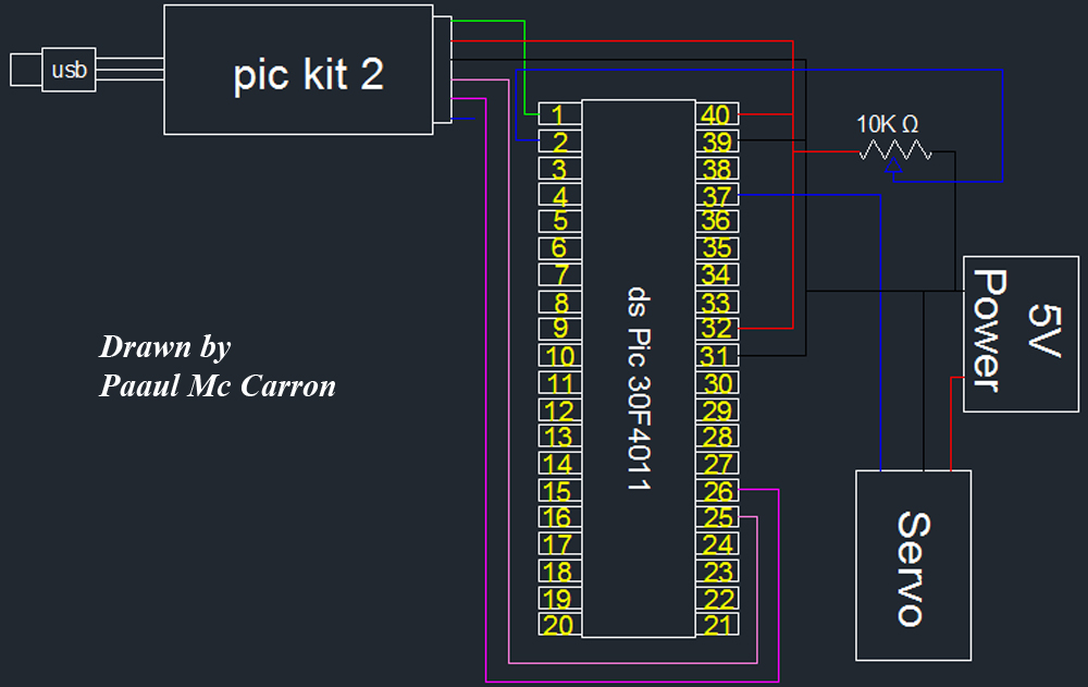
One of the motors utilized in the module is a servo motor. A servo motor is a compact motor that allows for precise positioning at various angles. It is equipped with internal circuitry that automatically maintains the specified angle....
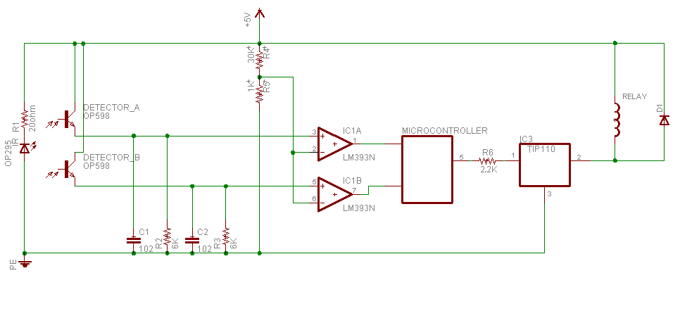
Sensing unit consists of infrared emitter OP295 to produce the infrared beam, and two detectors in front of the emitter to detect the infrared beam OP598. Since the main idea in this device is to know person direction; and...
Touch the sensor of the alarm with your finger, and it starts beeping. It continues for a period and then stops. Touching it again will activate the beeping once more. This description outlines a basic touch-activated alarm system. The...
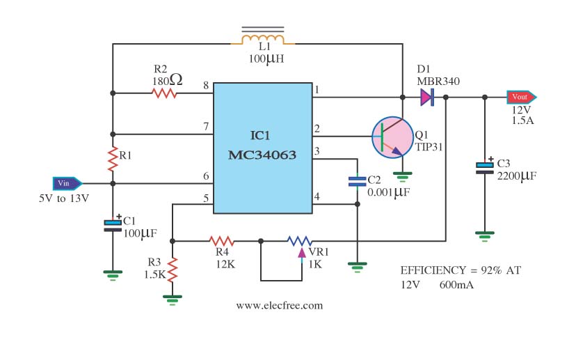
The circuit is a battery-powered voltage regulator that outputs 12V at 1.5A. It accepts an input voltage range from 5V to 13V. The circuit utilizes the MC34063 integrated circuit, making it a straightforward design. The circuit primarily functions as a...