
Spy Telephone
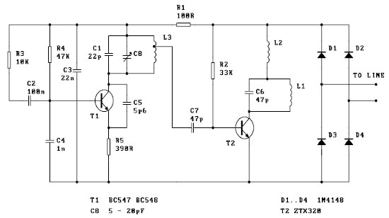
The FM spy telephone circuit operates by utilizing the existing phone line as a power source and an antenna for transmitting audio signals. The circuit is designed to be installed in series with the telephone line, allowing it to intercept audio signals without requiring an external power supply.
The core component of this circuit is the FM transmitter module, which modulates the audio signal picked up from the phone line into radio frequency signals. These signals are then emitted into the surrounding area via the phone line itself, which acts as an improvised antenna. The circuit typically includes essential elements such as capacitors for filtering, resistors for biasing, and possibly an operational amplifier to enhance the audio signal before modulation.
The circuit's operation hinges on the principle of frequency modulation (FM), where variations in the input audio signal cause corresponding variations in the frequency of the transmitted signal. This allows for a relatively clear transmission of voice or sound over short distances, making it suitable for covert audio surveillance applications.
Installation of this circuit requires careful consideration of legal and ethical implications, as unauthorized interception of telephone communications may violate privacy laws. Proper precautions and permissions should be obtained before deploying such a device. The simplicity of the design, combined with the ability to draw power directly from the phone line, makes this circuit an intriguing project for electronics enthusiasts interested in the fields of radio frequency and audio transmission.This FM spy telephone circuit is mounted serial with the phone line. When is signal on the wires this transmitter will radiate airwaves thru the wires which act as antenna. There is no need for batteries because it got his voltage supply from the phone lines. Be the first of your friends to get free diy electronics projects, circuits diagrams, hac ks, mods, gadgets & gizmo automatically each time we publish. Your email address & privacy are safe with us ! 🔗 External reference
Related Circuits
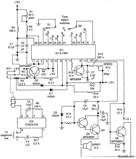
The core component of the circuit is IC1, the AY-3-1350 melody synthesizer IC from General Instrument. IC2 is a TCM1512 telephone ring detector IC powered by the telephone line. The circuit operates when IC2 detects a ring pulse on...
This telephone ringer utilizes an AMI chip with part number S2561 and can be powered directly from the telephone line. The audio output is approximately 50 mW when supplied with a 10-V source. The circuit design of the telephone ringer...
Offline telephone tester. This circuit allows for testing a telephone instrument without the need for a telephone line. The design is straightforward. The offline telephone tester circuit is designed to evaluate the functionality of telephone instruments independently of an active...
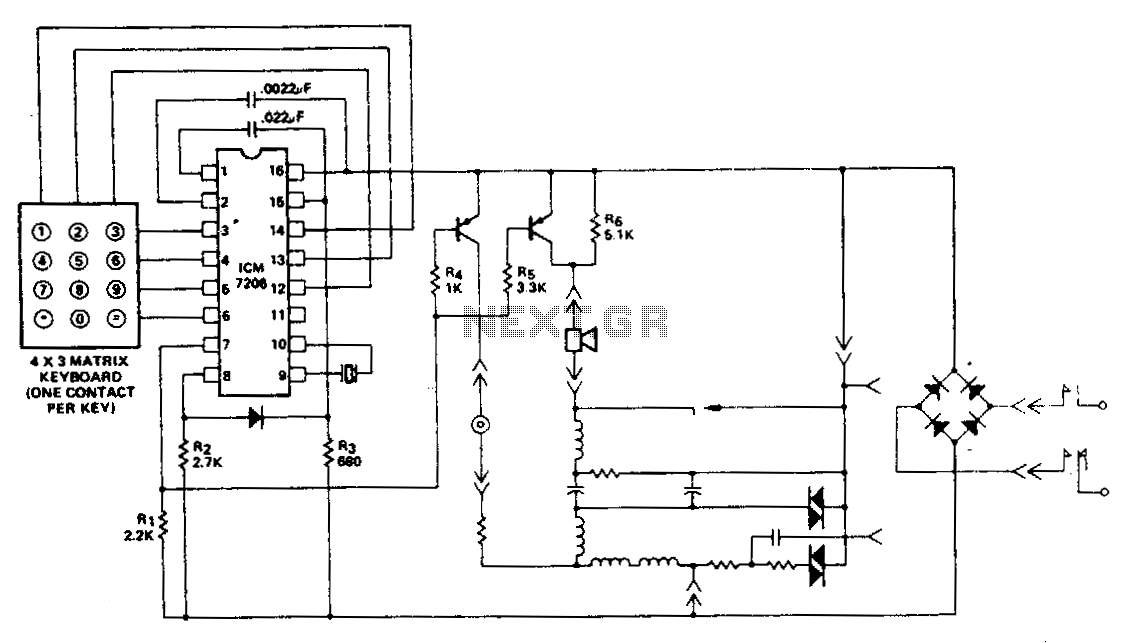
This encoder utilizes a single contact per key keyboard and manages all other switching functions electronically. A diode connected between terminals 8 and 15 limits the output to no more than 1 V negative concerning the negative supply, Vss....
This circuit will allow you to connect any tape recorder that has a mic and remote input to a phone line and automatically record both sides of a conversation whenever the phone is in use. You will need to...

Often, there is a need for an additional telephone ringer in an adjoining room to be alerted about incoming calls. For instance, if the telephone is situated in the drawing room, an extra ringer may be required in the...