
Audio interface for Telephone line
The described circuit effectively extracts audio signals from a telephone line while ensuring safety and compatibility with external equipment. The use of a transformer is critical for isolating the telephone line from the connected devices, which mitigates the risk of damage from voltage spikes or electrical interference.
The non-polarized capacitor, positioned in series with the transformer, plays a vital role in preventing direct current (DC) from flowing through the transformer winding. This is essential for maintaining the proper operational state of the telephone line, specifically allowing it to return to the on-hook state when not in use. The capacitor must be rated for voltages exceeding the combined peak ringing voltage of 90 volts and the on-hook voltage of 48 volts, leading to a recommended voltage rating of at least 400 volts to ensure reliability across varying local conditions.
The audio output level from the transformer is approximately 100 millivolts, suitable for connection to high impedance inputs such as amplifiers or tape recorders. For signal amplification, a three-transistor amplifier circuit can be employed, enhancing the audio signal while maintaining fidelity.
To protect the circuit from overvoltage conditions, particularly during ringing signals, two diodes are connected in parallel across the transformer’s secondary winding. These diodes serve as clamping devices, limiting the audio signal to a maximum of 700 millivolts peak, which safeguards downstream components from excessive voltage levels. Common silicon diode types, such as 1N400X, 1N4148, or 1N914, can be utilized for this purpose.
Finally, a 620-ohm resistor is included in the circuit design to minimize the loading effect on the telephone line when interfacing with low impedance loads. This resistor ensures that the line remains operational without significant signal degradation, thus preserving the integrity of the audio signal during transmission. Overall, this circuit design provides a robust solution for audio extraction from telephone lines, balancing performance with safety considerations.Audio from a telephone line can be obtained using a transformer and capacitor to isolate the line from external equipment. A non-polarized capacitor is placed in series with the transformer line connection to prevent DC current from flowing in the transformer winding which may prevent the line from returning to the on-hook state.
The capacitor should have a voltage rating above the peak ring voltage of 90 volts plus the on-hook voltage of 48 volts, or 138 volts total. This was measured locally and may vary with location, a 400 volt or more rating is recommended. Audio level from the transformer is about 100 millivolts which can be connected to a high impedance amplifier or tape recorder input. The 3 transistor amplifier shown above can also be used. For overvoltage protection, two diodes are connected across the transformer secondary to limit the audio signal to 700 millivolts peak during the ringing signal.
The diodes can be most any silicon type (1N400X / 1N4148 / 1N914 or other). The 620 ohm resistor serves to reduce loading of the line if the output is connected to a very low impedance. 🔗 External reference
Related Circuits
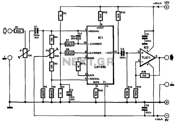
Often, the frequency of a signal must be doubled, and the modulator/demodulator chip LM1496 serves as an ideal basis for this application. From trigonometry, it is well known that 2sin(x)cos(x) = sin(2x) and sin^2(x) = 1 - cos^2(x). These...
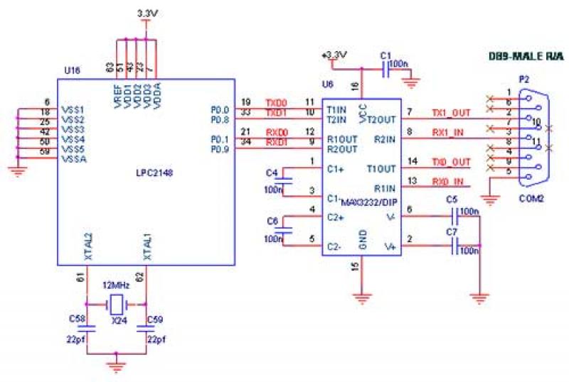
The interfacing of a Bluetooth module with the LPC2148 microcontroller is a straightforward process that enables the transmission of messages from the LPC2148 Primer Board to mobile devices via Bluetooth using UART0. Some delays may occur when sending a...
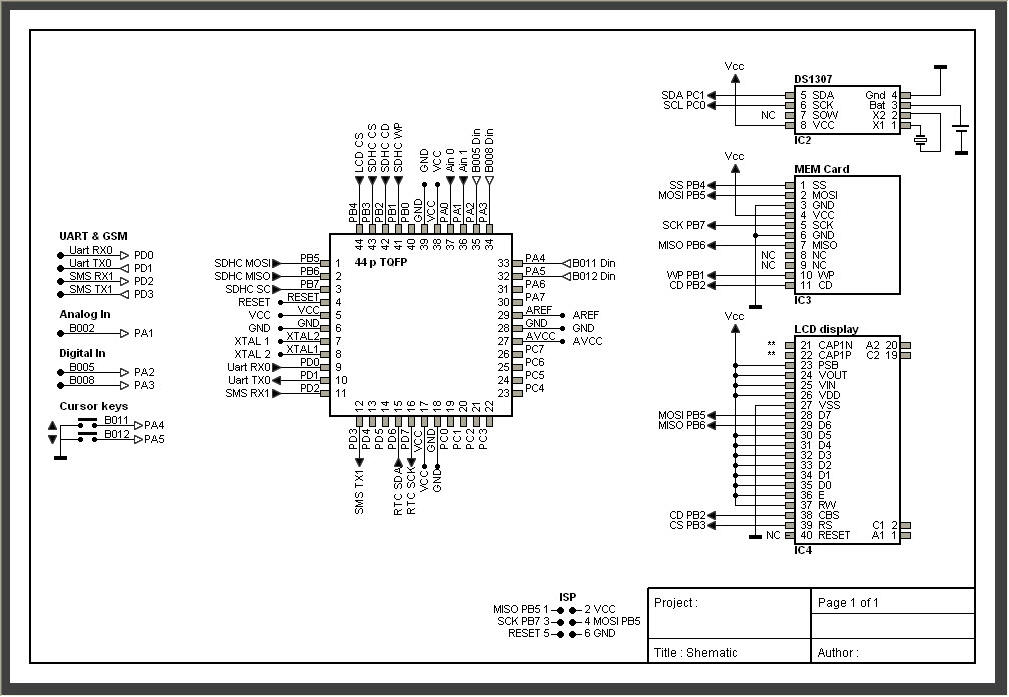
AVRtools features an intuitive graphical user interface and utilizes predefined function blocks. It provides a wide array of basic functions, including timers, counters, logic operations, and analog signal processing. Additionally, it includes function blocks for sending SMS messages over...
Many analog ohm meters have a non-linear scale, which results in poorer resolution at higher resistance values. This is due to the use of inexpensive current sources. Many analog ohm meters operate on a principle where the scale is not...
Below are three examples of controlling a relay from the PC's parallel printer port (LPT1 or LPT2). Figure A shows a solid-state relay controlled by one of the parallel port data lines (D0-D7) using a 300-ohm resistor and a...
Many low-power SSB (Single Sideband) transceivers and kits lack effective speech processor circuitry, despite the presence of built-in speech processors in most modern HF (High Frequency) equipment. Low-power SSB transceivers are popular among amateur radio enthusiasts due to their compact...