
telephone number display circuit diagram

The circuit operates by utilizing the DTMF signaling system, which is standard in telephone communication. The CM8870P1 decoder IC is pivotal in translating the audible tones generated by the telephone into a digital format that can be processed and displayed. The sequential storage of dialed numbers in latches allows for easy retrieval and display of the most recent numbers dialed, enhancing usability for monitoring and logging call activity. The use of the CD4508 dual 4-input AND gate facilitates the logic conversion necessary for handling the unique case of the digit zero, ensuring that all digits can be displayed correctly on the seven-segment displays.
The IC4017 decade counter plays a crucial role in managing the storage and retrieval of the dialed numbers, effectively sequencing through the latches to ensure that data is stored and displayed in the correct order. The integration of a single seven-segment decoder reduces component count and simplifies the circuit design, while the use of transistors for display control allows for efficient switching and power management.
Overall, this circuit presents a practical solution for displaying dialed telephone numbers, providing a clear interface for users to view call information. Its design can be tailored to specific needs, such as reducing display digits or customizing display colors, making it a versatile tool in telecommunications applications.The given circuit, when connected in parallel to a telephone, dis- plays the number dialled from the telephone set using the DTMF mode. This circuit can also show the number dialled from the phone of the called party. This is particularly helpful for receiving any number over the phone lines. The DTMF signal generated by the phone on dialling a nu mber is decoded by DTMF decoder CM8870P1 (IC1), which converts the received DTMF signal into its equivalent BCD number that corresponds to the dialled number. This binary number is stored sequentially in 10 latches each time a number is dialled from the phone.
The first number is stored in IC5A (1/2 of CD4508) while the second number is stored in IC5B and so on. The binary output from IC1 for digit 0 as decoded by IC1 is 10102 (=1010), and this cannot be displayed by the seven-segment decoder, IC10.
Therefore the binary output of IC1 is passed through a logic-circuit which converts an input of 10102 into 00002 without affecting the inputs 1 through 9. This is accomplished by gates N13 through N15 (IC11) and N1 (IC12). The storing of numbers in respective latches is done by IC2 (4017). The data valid output from pin 15 of IC1 is used to clock IC2. The ten outputs of IC2 are sequentially connected to the store and clear inputs of all the latches, except the last one, where the clear input is tied to ground.
When an output pin of IC2 is high, the corresponding latch is cleared of previous data and kept ready for storing new data. Then, on clocking IC2, the same pin becomes low and the data present at the inputs of that latch at that instant gets stored and the next latch is cleared and kept ready.
The similar input and output pins of all latches are connected together to form two separate input and output buses. There is only one 7-segment decoder/driver IC10 for all the ten displays. This not only reduces size and cost but reduces power requirement too. The output from a latch is available only when its disable pins (3 and 15) are brought low. This is done by IC3, IC12 and IC13. IC3 is clocked by an astable multivibrator IC4 (555). IC3 also drives the displays by switching corresponding transistors. When a latch is enabled, its corresponding display is turned on and the content of that latch, after decoding by IC10, gets displayed in the corresponding display.
For instance, contents of IC5A are displayed on display DIS1, that of IC5B on DIS2 and so on. The system should be connected to the telephone lines via a DPDT switch (not shown) for manual switching, otherwise any circuit capable of sensing handset s off-hook condition and thereby switching relays, etc. can be used for automatic switching. The power-supply switch can also be replaced then. Though this circuit is capable of showing a maximum of ten digits, one can reduce the display digits as required.
For doing this, connect the reset pin of IC2, say, for a 7-digit display, with S6 output at pin 5. The present circuit can be built on a veroboard and housed in a suitable box. The displays are common-cathode type. To make the system compact, small, 7-segment displays can be used but with some extra cost. Also, different colour displays can be used for the first three or four digits to separate the exchange code/STD code, etc. The circuit can be suitably adopted for calling-line display Disclaimer: All the information present on this site are for personal use only.
No commercial use is permitted without the prior permission from authors of this website. All content on this site is provided as is and without any guarantee on any kind, implied or otherwise. We cannot be held responsible for any errors, omissions, or damages arising out of use of information available on this web site.
The content in this site may contain COPYRIGHTED information and should not be reproduced in any way without prior permission from the authors. 🔗 External reference
Related Circuits
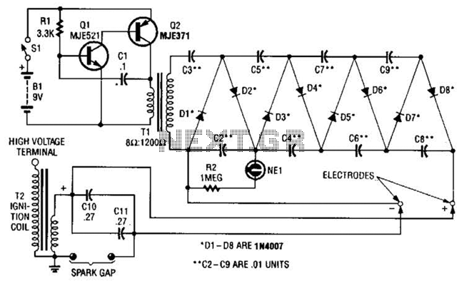
This circuit employs a transistor oscillator and a voltage multiplier to charge capacitors CIO and CI1 to a high voltage. When the spark gap breaks down, T2 generates a high-voltage pulse through the discharge of capacitors CIO and CI1...

More: The input data contains a brief description with no additional context or information provided. In the realm of electronics, a circuit schematic typically serves as a visual representation of an electrical circuit. It illustrates the various components such...
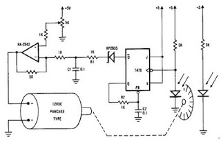
A simple encoder circuit for a DC motor can be constructed using the provided circuit diagram. The system includes the HA-2542 operational amplifier, a small 12 V DC motor, and a position encoder. During operation, the encoder generates a...
In the presence of combustible gas, the conductance of the TGS308 gas sensor increases, causing the voltage at the potentiometer RP1 slide point to rise from a normal 3V RMS to 20V. This elevated voltage is applied to transistor...
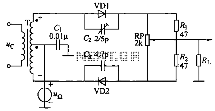
A common diode balanced modulator circuit is illustrated. It comprises two identical performance diodes and a center-tapped transformer configuration. The diodes used are VD1 and VD2, specifically 2AP9 models. The parameters for the circuit elements are detailed in FIG....
This circuit generates a two-tone effect similar to the cuckoo song. It can be utilized for doorbells or other applications due to its integrated audio amplifier and loudspeaker. As a sound effect generator, it can connect to external amplifiers,...
Warning: include(partials/cookie-banner.php): Failed to open stream: Permission denied in /var/www/html/nextgr/view-circuit.php on line 713
Warning: include(): Failed opening 'partials/cookie-banner.php' for inclusion (include_path='.:/usr/share/php') in /var/www/html/nextgr/view-circuit.php on line 713