
Telephone Remote control
The circuit utilizes several integrated circuits (ICs) to facilitate remote appliance control via telephone lines. Key components include the KT3170, which functions as a DTMF-to-BCD converter, a 74154 4-to-16 line demultiplexer, and five CD4013 D flip-flops.
The operational sequence begins when a call is established and the user hears a ring-back tone. The user must then dial '0' in DTMF mode, which is processed by the KT3170 (IC1). The IC decodes the DTMF signal '0' as the binary code 1010. This output is then sent to the 74154 demultiplexer (IC2), which demultiplexes this code to activate output O10 (pin 11). The active low output from IC2 is inverted by an inverter gate from a CD4049 (IC3), resulting in a logic high signal. This logic high toggles the first flip-flop (F/F-1), energizing relay RL1.
Relay RL1 is crucial for the operation, as it features two changeover contacts: RL1(a) and RL1(b). When RL1(a) is energized, it creates a 220-ohm loop across the telephone line, disconnecting the ringer from the line. Simultaneously, RL1(b) injects a 10kHz tone onto the line, signaling to the caller that the appliance mode has been activated. This setup allows the telephone line to be repurposed for appliance control while still maintaining the ability to engage in normal conversations when appliance mode is not selected.
If the digit '0' is not dialed after the call is established, the phone remains in normal operation, allowing for uninterrupted conversation. Once appliance mode is activated, dialing any digit from '1' to '9' sends a corresponding DTMF signal. For example, dialing '1' is decoded to the binary output 0001 by IC1. This output is then demultiplexed by IC2, activating the associated output, which is inverted to produce a logic high signal, toggling the corresponding flip-flop. The output from this flip-flop drives relay RL2, which controls the power to the appliance connected through its contacts, thus enabling the switching on or off of that specific appliance.
After completing the desired switching operations, the user must revert the system back to normal operation. This is done by dialing '0' again in DTMF mode. This action toggles flip-flop-1, de-energizing relay RL1 and removing both the 220-ohm loop and the 10kHz tone from the telephone line. Consequently, the telephone line is restored for normal calls.
The entire circuit is designed to be connected in parallel to the existing telephone instrument, ensuring that it does not interfere with regular telephone functionality while providing the added capability of remote appliance control.Here is a teleremote circuit which enables switching on and off of appliances through telephone lines. It can be used to switch appliances from any distance, overcoming the limited range of infrared and radio remote controls.
The circuit described here can be used to switch up to nine appliances (corresponding to the digits 1 through 9 of the telephone key-pad). The DTMF signals on telephone instrument are used as control signals. The digit 0 in DTMF mode is used to toggle between the appliance mode and normal telephone operation mode.
Thus the telephone can be used to switch on or switch off the appliances also while being used for normal conversation. The circuit uses IC KT3170 (DTMF-to-BCD converter), 74154 (4-to-16-line demult-iplexer), and five CD4013 (D flip-flop) ICs. The working of the circuit is as follows. Once a call is established (after hearing ring-back tone), dial 0 in DTMF mode. IC1 decodes this as 1010, which is further demultiplexed by IC2 as output O10 (at pin 11) of IC2 (74154).
The active low output of IC2, after inversion by an inverter gate of IC3 (CD4049), becomes logic 1. This is used to toggle flip-flop-1 (F/F-1) and relay RL1 is energised. Relay RL1 has two changeover contacts, RL1(a) and RL1(b). The energised RL1(a) contacts provide a 220-ohm loop across the telephone line while RL1(b) contacts inject a 10kHz tone on the line, which indicates to the caller that appliance mode has been selected. The 220-ohm loop on telephone line disconnects the ringer from the telephone line in the exchange. The line is now connected for appliance mode of operation. If digit 0 is not dialed (in DTMF) after establishing the call, the ring continues and the telephone can be used for normal conversation.
After selection of the appliance mode of operation, if digit 1 is dialed, it is decoded by IC1 and its output is 0001. This BCD code is then demultiplexed by 4-to-16-line demultiplexer IC2 whose corresponding output, after inversion by a CD4049 inverter gate, goes to logic 1 state.
This pulse toggles the corresponding flip-flop to alternate state. The flip-flop output is used to drive a relay (RL2) which can switch on or switch off the appliance connected through its contacts. By dialing other digits in a similar way, other appliances can also be switched on or off. Once the switching operation is over, the 220-ohm loop resistance and 10kHz tone needs to be removed from the telephone line.
To achieve this, digit 0 (in DTMF mode) is dialed again to toggle flip-flop-1 to de-energise relay RL1, which terminates the loop on line and the 10kHz tone is also disconnected. The telephone line is thus again set free to receive normal calls.This circuit is to be connected in parallel to the telephone instrument.
🔗 External reference
Related Circuits
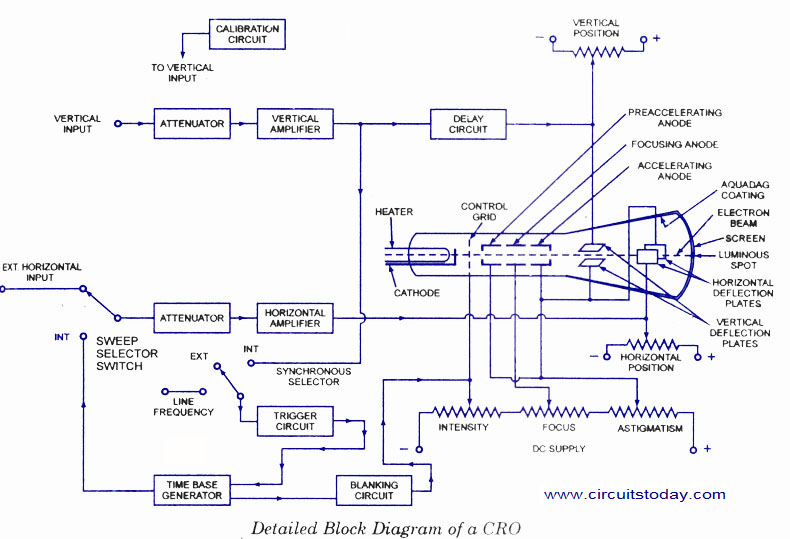
The number of controls required on a panel of a Cathode Ray Oscilloscope (CRO) is essential for its proper functioning. Intensity control is provided to adjust the brightness of the spot on the screen by varying the voltage between...
A telephone ringer capable of making any mains-powered device operate from the ringer of a fixed line telephone. This device allows the control of a high-powered siren or horn to amplify the low-level sound of a telephone, making it...
This Project is made up with AT89C2051 and the RTC DS1307. It has a large Seven segment display. The standard remote control is used to change the Time. More: Procedure to enter the Time 1. Press power button on...
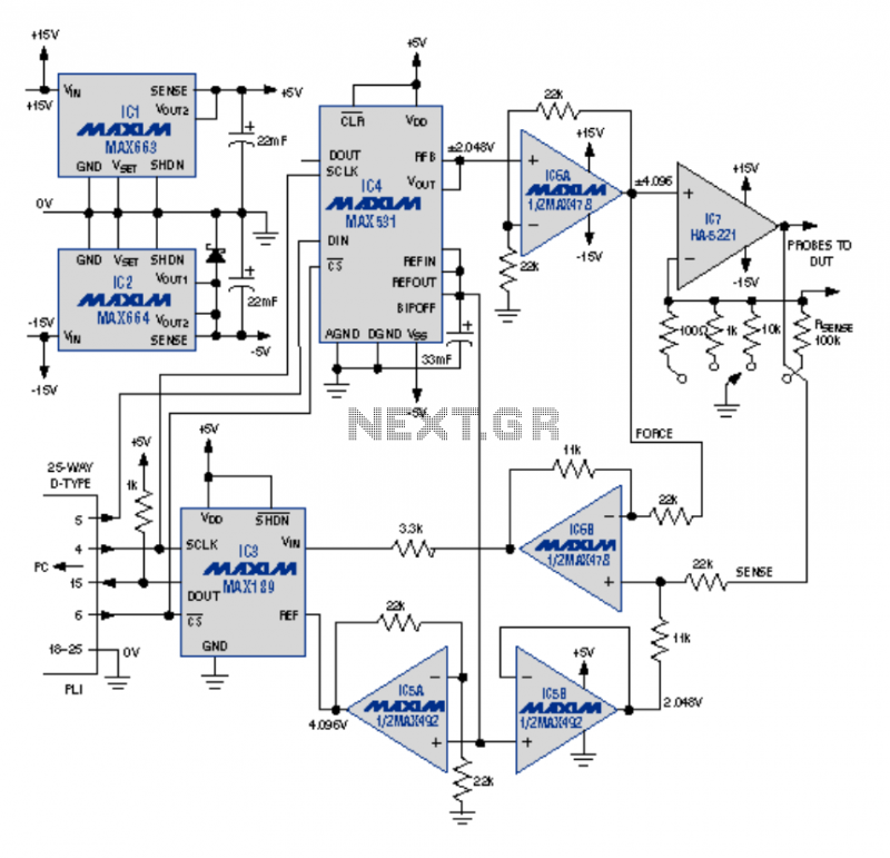
This article describes an I-V curve tracer circuit that uses a computer for display and control. The circuit is controlled via the PC parallel port. Software is provided, written in BASIC, to control the measurement and display the results...

Controlling the speed of a three-phase AC motor is achieved by regulating the frequency of the power supply, as the motor operates in synchronization with the line frequency. A three-phase AC motor speed controller functions as a three-phase sine...
This integrated circuit is highly efficient and does not require any external glue logic for operation. It features two pins to control a motor: one for direction and the other for stepping pulse triggers. The design is compact and...