
3 phase ac motor speed control circuit

The three-phase AC motor speed controller is implemented through a sine wave inverter, which converts the DC supply voltage into a three-phase AC output with adjustable frequency. The core of the circuit typically includes a microcontroller or a digital signal processor (DSP) that generates the required PWM (Pulse Width Modulation) signals to control the switching devices, such as MOSFETs or IGBTs, in the inverter stage. These devices are arranged in a three-phase bridge configuration to produce the necessary output waveforms.
The integrated circuit chip designed for this purpose simplifies the control of the inverter, allowing for precise frequency adjustments that directly influence motor speed. The PWM technique modulates the duty cycle of the output signals, effectively controlling the voltage applied to the motor. This modulation results in a variable frequency output, which is essential for speed control.
Optical isolation is implemented using opto-isolators to protect the low voltage control circuit from the high voltage power circuit. This is critical for ensuring operator safety and protecting sensitive components from voltage spikes or transients. The layout of the circuit must be meticulously designed, ensuring that high and low voltage traces are adequately separated to prevent interference and reduce the risk of electrical shock.
In the final design, careful consideration of component ratings, thermal management, and filtering techniques is necessary to enhance the reliability and efficiency of the motor controller. The selection of appropriate capacitors, inductors, and heat sinks will play a significant role in the overall performance and longevity of the device. Furthermore, implementing feedback mechanisms, such as current sensing and speed feedback loops, can improve the control accuracy and responsiveness of the motor speed controller.Controlling the speed of three phase ac motor is done by controlling the frequency of the power line supply, since the motor is synchronized with the line frequency. Three phase ac motor speed controller is actually nothing more than three phase sine wave power inverter with variable frequency.
The three phase power inverter is a complex circuit, but fortunately there is an integrated circuit chip for this purpose. This is the figure of the circuit; For the final motor driver circuit, you can see the component values are shown only for OB2 channel, but the others are similar. This 3 phase ac motor controller use optical isolation, so you must be careful in designing the layout, to make a clear separation between low and high voltage network.
This separation is useful for minimizing the risk of hazardouz electrical shock. 🔗 External reference
Related Circuits
This circuit generates dual-tone bell ringing similar to most doorbell units. It can be used in various applications beyond just doorbells. Several options will be provided in the notes to accommodate different needs. The circuit, as depicted in the...
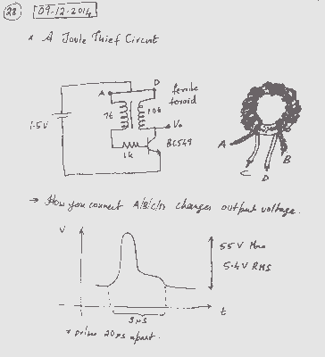
A simple voltage boost circuit known as the Joule Thief has been identified for construction. The Joule Thief is a minimalist boost converter designed to extract energy from low-voltage sources, such as depleted batteries, and increase the voltage to a...
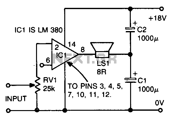
The ground side of the speaker is connected to the junction of two equal high-value capacitors (1000 µF is typical) across the supply. The amplifier output voltage will be Vs/2, and the voltage across CI (if CI and C2...
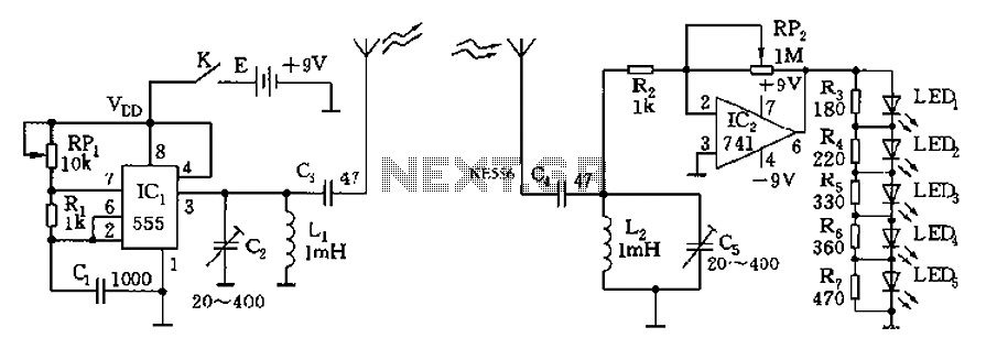
The circuit diagram of the device features a 555 timer IC configured as a transmitter and a receiver, divided into two sections. The 555 timer in the transmitter section serves as the core component of a frequency oscillator. The...
This circuit demonstrates a dynamic AC signal level display drive, which can be utilized for audio level display purposes. The AC signal detection and drive control are achieved using the BA6124 integrated circuit, along with five external colored light-emitting...
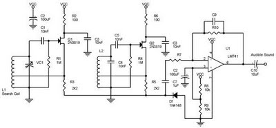
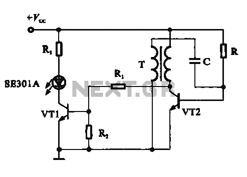
One type of metal detector is a beat frequency oscillator (BFO). The operation of metal detectors relies on changing the characteristics of the oscillator when it is near a metal object detected by the sensor. The detector functions based...
Warning: include(partials/cookie-banner.php): Failed to open stream: Permission denied in /var/www/html/nextgr/view-circuit.php on line 713
Warning: include(): Failed opening 'partials/cookie-banner.php' for inclusion (include_path='.:/usr/share/php') in /var/www/html/nextgr/view-circuit.php on line 713