
Telephone Ringer Circuit
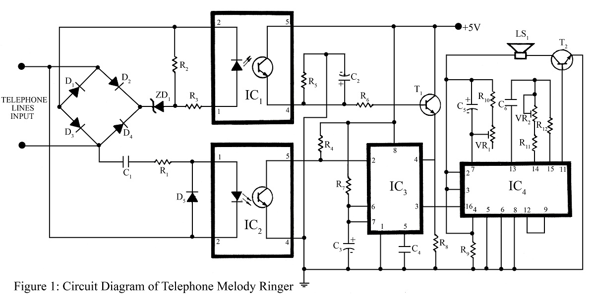
The telephone ringer circuit operates by utilizing a combination of analog components and integrated circuits to create a musical response to incoming calls. The use of the UM3481/3482/3483/3484 series IC allows for the storage and playback of multiple melodies, enhancing the user experience compared to traditional ringing mechanisms. The bridge rectifier ensures that the circuit remains functional regardless of the polarity of the telephone line connection, which is crucial for maintaining reliability in various installation scenarios.
The voltage divider formed by the zener diode and resistor network is critical for adapting the high voltage from the telephone line to a level that is safe and suitable for triggering the opto-coupler. This ensures that the circuit can accurately detect the ringing signal without damage. The inclusion of capacitors to block DC while allowing AC signals to pass is a standard practice in telephone circuits, as it prevents interference from the DC voltage present when the line is idle.
The monostable multivibrator configuration of the timer IC allows the circuit to respond to the first ring only, preventing repetitive triggering from subsequent rings. This design choice ensures that the musical output is limited to a single sequence per incoming call, which is more pleasant and less disruptive.
The modulation components, including variable resistors and capacitors, provide flexibility in sound generation, allowing the user to customize the auditory experience. This adaptability is a significant advantage, as it enables the circuit to emulate a variety of musical tones, catering to different preferences.
Overall, the telephone ringer circuit represents a thoughtful integration of electronic components aimed at enhancing the traditional telephone ringing experience with musical elements, while also ensuring robust performance through careful design considerations.The Telephone project posted here is the a telephone ringer which producespleasanttunes when a call is placed to your number. The tunes produced by telephone ringer here are more melodious andsoothing compare to those of old telephone instrument and piezo buzzer in the current electronic telephone instruments.
The circuit is based on the musica l IC UM3481/3482/3483/3484 (IC4). When the telephone senses an incoming cal signal, all the tunes stored in the ROM of the IC (IC4) are played in sequence. The bell stops ringing when handset is picked up. The complete circuit comprises of music IC, timer IC, a pair of opto-coupler followed by few other components as shown in circuit diagram (Figure 1).
Diode D1 through D4 configured as bridge rectifier through which telephone line is connected. The bridge rectifier provides correct polarity to the LED inside the opto-coupler of IC1, even if the telephone line is connected in wrong polarity by accident. As we all know that in idle or on-hook condition of telephone, there is about -48 volts DC through the telephone line.
The divider network is formed by combining zener diode ZD1 with resistor R2 which divides the DC voltage from telephone line. The divided voltage is again reduced by resistor R3. The reduced output voltage from resistor R3 is sufficient to light the LED inside IC1. The internal transistor of IC1 only conducts when internal LED glow and also aids transistor T1 to conduct.
Hence the supply voltage is extended to the reset pin 4 of timer IC (IC3). The output of IC3 at pin 3 becomes low when the pin 2 is in high` condition. Capacitor C1 across the telephone line blocks the DC voltage of about -48 volts (because capacitor blocks DC voltage and can let only AC volts) and prevents it from reaching the telephone ring sensing circuit build around IC2. Diode D5 connected across IC2 protects the internal LED of IC2 during arrival of the ringing signal. The internal LED of IC2 glow when ringing signal is present and cause internal transistor to conduct, thereby extending low` to pin 2 of IC3.
The timer IC (IC3) is configured as monostable multivibrator. The low input at pin 2 operates and extends a high` into its output at pin 3. The output of monostable multivibrator is act as power supply for the music circuit designed around musical IC (IC4). The output of IC3 is high for a period determined by the value of R7 and C3. During this period, IC4 generates pleasant tunes. IC3 responds only to the first ring and ignores subsequent rings during the timing cycle because it is configured as monostable multivibrator, and thus allowing IC4 to produces tunes for the entire time period.
The potential drop at telephone line becomes 5-6 volts due to the impedance of the telephone instrument when the telephone is answered or is off-hook`. The low potential drop prevents zener diode ZD1 to connect and hence the LED inside IC1 turns off. This, in turn, switches off the internal transistor and transistor T1. When transistor T1 is turned off, the reset voltage at pin 4 of IC3 is removed, which further withdraw the power supply of the music circuit and the melody stopped.
When the output is high at pin 3 of IC3, pin 4 of IC4 triggers it into operation. Resistor R10, variable resistor VR1 with capacitor C5 changes the internal modulation of the music IC. This is done because lets the IC4 to sound like different music instruments such as piano and organ. Resistors R11, R12, variable resistor VR1 with capacitor C6 determine the frequency of internal oscillator of IC4.
These components change the speed of tempo of tune. Variable resistor VR2 is used to adjust the speed at which the tune is played. Larger and lower the value of capacitor C6 slows and increases the speed of the beat. Note: While testing the circuit Telephone Melody Ringer in LAB we found that the main drawback of this circuit is, sometimes during dialing a melodeous tone may be heard. 🔗 External reference
Related Circuits
A simple USB-powered lamp designed to illuminate a desktop during power outages. The circuit operates at 5 volts sourced from a USB port. The 5V from the USB is directed through a current-limiting resistor (R2) and a transistor (Q1)....
The circuit output voltage can be continuously adjusted from zero to its maximum value. The baseline is established by a constant current sourced from the auxiliary power supply circuit. The reference current of 500 microamperes can be fine-tuned to...
A DIY GSM jammer schematic diagram designed specifically for GSM1900 frequencies ranging from 1930 MHz to 1990 MHz. The GSM1900 mobile phone network is utilized in the USA, Canada, and most South American countries. This cell phone jammer is...
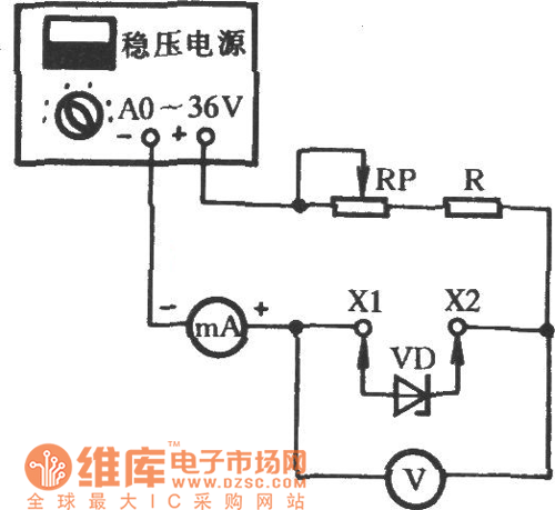
Connect the diode VD under test to sockets X1 and X2. A stabilized power supply applies reverse breakdown voltage to VD, allowing the stabilized voltage value Uz to be read from voltage meter V. The stable operating current value...

The remote control circuit consists of two main components: the transmitter and the receiver. A simple schematic diagram illustrates the remote control setup. The transmitter circuit utilizes a NE555 timer IC to generate a specific frequency. The receiver circuit...
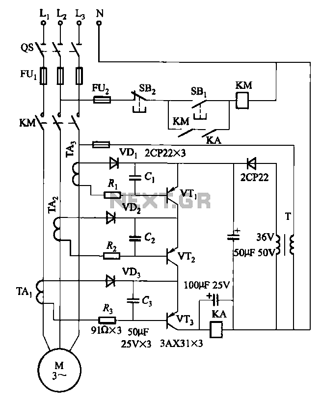
Drawing transistors that comprise the gate VTi, VT2, VT3, and similar components. The schematic involves a configuration of transistors designated as VTi, VT2, and VT3, which are integral to forming a gate structure. These transistors are typically arranged in a...
Warning: include(partials/cookie-banner.php): Failed to open stream: Permission denied in /var/www/html/nextgr/view-circuit.php on line 713
Warning: include(): Failed opening 'partials/cookie-banner.php' for inclusion (include_path='.:/usr/share/php') in /var/www/html/nextgr/view-circuit.php on line 713