
usb lamp circuit
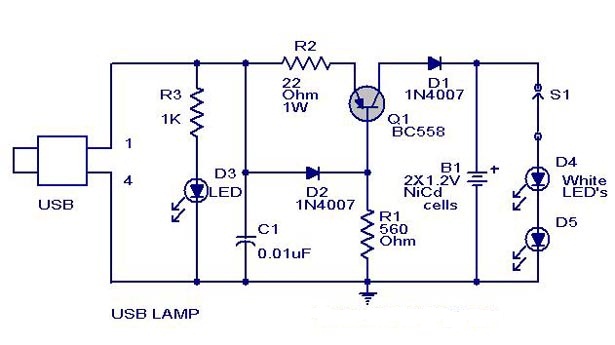
This USB-powered lamp circuit is designed to provide a reliable light source during power interruptions, utilizing the standard 5V supply from USB ports, commonly found in various electronic devices. The circuit's core components include a current-limiting resistor (R2) that ensures the appropriate current flows through the transistor (Q1) and the connected load, preventing damage to sensitive components.
Transistor Q1 operates as a switch, controlled by the biasing provided through resistor R1. This resistor is crucial for maintaining the transistor in its active region, allowing it to turn on and off in response to the voltage levels at its base. The inclusion of diode D2 serves to stabilize the circuit by providing a reference voltage, ensuring that Q1 remains in the desired operational state.
Diode D1 is strategically placed to prevent any reverse current that may occur from the battery, protecting the circuit from potential damage. Capacitor C1 acts as a noise filter, smoothing out any voltage fluctuations that could affect the performance of the LEDs or other circuit components.
The lamp utilizes two white LEDs, which are efficient light sources and consume less power compared to traditional incandescent bulbs. However, a 2V torch bulb can be substituted if desired, offering flexibility in terms of light output and design. The circuit also includes an indicator LED (D3) that visually confirms the connection to the USB power source, enhancing user experience by providing a clear signal of operational status.
In summary, this circuit combines simple yet effective components to create a practical USB-powered lamp capable of functioning during power outages, with thoughtful design considerations for component protection and user feedback.A simple USB powered lamp that can be used to light your desktop during power failures. The circuit operates from the5 Voltavailable from the USB port. The 5V from the USB port is passed through current limiting resistor R2 and transistor Q1. The base of transistor Q1 is grounded via R1 which provides a constant bias voltage for Q1 together w ith D2. The diode D1 prevents the reverse flow of current from battery. C1 is used as a noise filter. Two white LED`s are used here for the lamp, you can also use a 2 V torch bulb instead of LED`s. LED D3 indicates connection with USB port. 🔗 External reference
Related Circuits
The 27MHz crystal oscillator circuit is illustrated in the figure. Resistors R1, R2, and R3 serve as biasing resistors, while capacitor C6 functions as a bypass capacitor. The voltage division circuit consists of capacitors C1, C3, C4, and C2,...
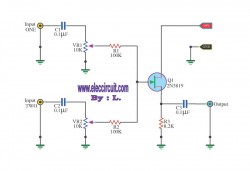
This circuit is a simple mixer circuit that can mix two signal channels into one output channel. It utilizes a codec circuit to convert stereo audio into mono audio. Additionally, the circuit can increase the number of channels by...
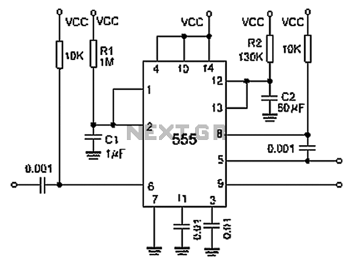
A 0.001 F coupling capacitor connects the output of the first half of a 556 timer to the input of the second half, providing an individual delay that equals the total delay. The 6-foot ground can immediately activate the...
A user has been experimenting with modifications to a budget-friendly MXL V67s microphone to enhance its performance, specifically aiming to improve the condenser quality until a higher-end model can be acquired. The MXL V67s is a popular choice among budget-conscious...
The electronic pest-killing lamp circuit comprises an oscillator, control circuit, high voltage generator, LED indicator circuit, and power supply circuit. The schematic diagram illustrates these components. The oscillator circuit includes a time-base integrated circuit (IC), resistors R5 to R7,...
This simple circuit tests speakers, microphones, transformers, and voltage. It is essentially a very low-frequency oscillator that produces extremely short "fruity" pulses. The sound produced is easy to hear and allows for precise determination of its direction, making it...