
Adjustable output voltage of the series regulator circuit diagram
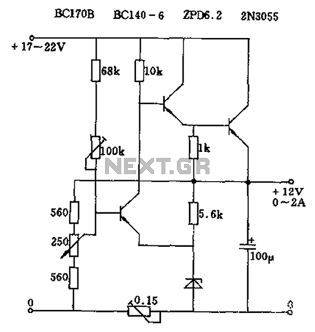
The described circuit employs a potentiometer to facilitate the adjustment of the output voltage. The 2.5k ohm potentiometer serves as a variable resistor, enabling fine control over the current flowing through it. When the reference current of approximately 7mA is established, the voltage across the potentiometer can be calculated using Ohm's Law (V = I × R). As the resistance is varied, the voltage drop across the potentiometer changes, thus allowing the output voltage (Ua) to be modulated between zero and its maximum value.
In practical applications, this configuration is commonly used in power supply circuits where a variable output voltage is required. The constant current source ensures stability in the output, preventing fluctuations that could arise from varying load conditions. Additionally, the use of a potentiometer allows for easy manual adjustments, making it suitable for applications where precise voltage settings are necessary.
To enhance the performance of this circuit, consideration should be given to the power ratings of the components used, particularly the potentiometer, to ensure they can handle the maximum current without overheating. Furthermore, circuit protection mechanisms, such as fuses or current limiting resistors, may be incorporated to safeguard against potential overload situations. Overall, this circuit design offers a reliable solution for applications requiring adjustable voltage outputs. Circuit output voltage can be continuously adjusted from zero to maximum. Its baseline is a constant current from the auxiliary power supply circuit. 500 Europe reference curre nt can be adjusted to fine-tune the resistance, and its value should be around 7mA. This current flows through the 2.5k Europe potentiometer and the voltage drop is formed from zero to maximum output voltage thereon, so that the output voltage Ua can be continuously adjustable from zero to maximum.
Related Circuits
The aboriginal accessory forms a typical oscillator circuit that produces both a triangle waveform signal and a square wave signal. The triangle signal is fed into a voltage regulator circuit, which converts the triangle voltage signal to a triangle...
There are three switches that represent a binary number, and according to the combination of those switches, the number of lit LEDs changes to represent that binary number. There is a question regarding how to provide equal current and...
Logic Gates FM Transmitter Circuit Electronic Circuit Schematic Wiring Diagram. The FM transmitter circuit utilizing logic gates is a fundamental electronic design that operates by modulating a carrier frequency with an audio signal. This circuit typically consists of various logic...
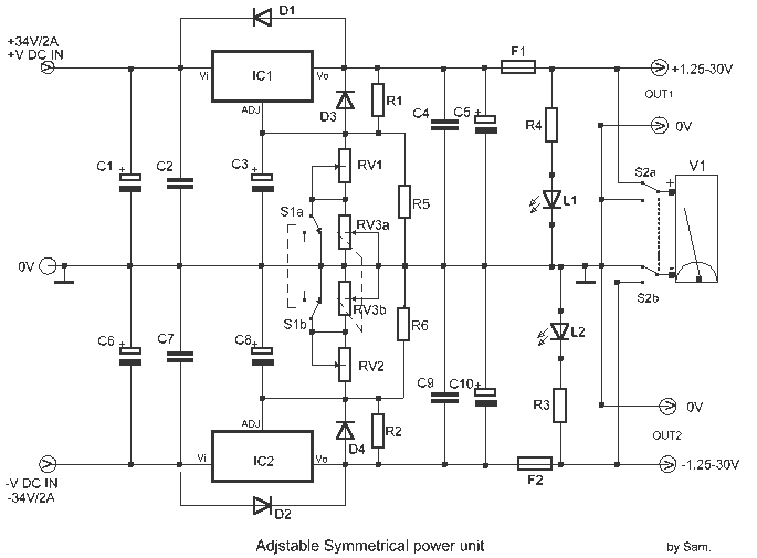
This is the voltage converter to get the voltage of ±1.25-30V from the input voltage of ±35V. I am using the 3 terminal voltage regulator for the voltage to be changed in this unit. As the regulator, LM317 is...
This site addresses a range of subjects pertaining to circuits and electronics. Some of the topics discussed on this site include: * Alternating Relay Switch * Photoswitch Relay. The site serves as a comprehensive resource for understanding various electronic components...
To prevent the failure of electric contact pressure thermometer contacts due to singeing, it is advisable to enhance the contacts, as illustrated in Fig. 11-60. Specifically, the output termination table for DC control utilizes two two-way thyristors or a...
Warning: include(partials/cookie-banner.php): Failed to open stream: Permission denied in /var/www/html/nextgr/view-circuit.php on line 713
Warning: include(): Failed opening 'partials/cookie-banner.php' for inclusion (include_path='.:/usr/share/php') in /var/www/html/nextgr/view-circuit.php on line 713