
Telephone ringing detector
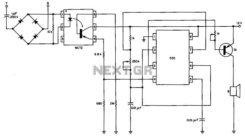
The circuit utilizes the 555 timer in astable mode to generate a continuous square wave output. This output is then used to control the opto-isolator, which serves as a bridge between the low-voltage control circuit and the high-voltage speaker circuit. The opto-isolator provides electrical isolation, protecting the low-voltage components from high-voltage spikes that may occur in the speaker circuit.
The 555 timer's frequency and duty cycle can be adjusted by varying the resistor and capacitor values connected to its timing pins. Typically, two resistors (R1 and R2) and one capacitor (C1) are connected to pins 6, 2, and 3 of the 555 timer. The output from the 555 timer (pin 3) is connected to the input of the opto-isolator. The opto-isolator consists of an LED and a phototransistor; when the LED is activated by the timer's output, it triggers the phototransistor, allowing current to flow through the speaker circuit.
In this configuration, the remote speaker can be effectively driven by the signal generated from the 555 timer, ensuring that the speaker receives the necessary power without direct electrical connection to the control circuit. This design is particularly useful in applications where isolation is crucial, such as in remote control systems or in environments with high electrical noise.With the 555 timer connected as a multivibrator and an opto-isolator, a remote speaker can be driven. 🔗 External reference
Related Circuits
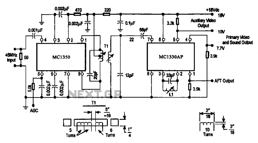
The circuit features an IF processing section utilizing the MC1350 and a video detector, the MC1330AP, which are integrated to form a combined video processing system. The modulation of the circuit is dependent on the image signal, with the...
This circuit will detect AC line currents of about 250 mA or more without making any electrical connections to the line. Current is detected by passing one of the AC lines through an inductive pickup (L1) made with a...
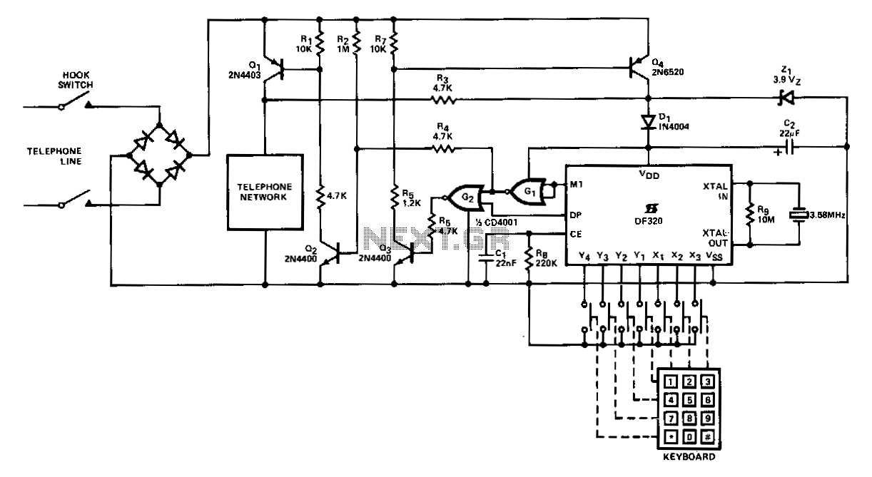
When the handset is lifted and power is applied to the circuit, Q2 receives base current through R2, which subsequently activates Q1. Capacitor C2 charges via resistor R3 in series with diode D1 to a voltage of (Vz1 -...
The circuit automatically lights a bulb upon the arrival of a telephone ring and simultaneously mutes the audio from the music system or TV while the telephone handset is off-hook. The lighting of the bulb not only indicates an...
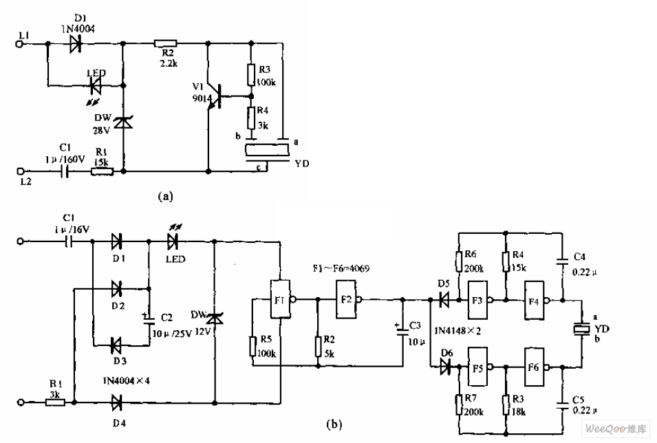
The telephone electronic ringer circuit is illustrated in the provided figure. It features an NPN transistor (either 9014 or 3DG12) as the primary component. The sound device, referred to as YD, functions as both a feedback device and is...
The circuit shown here is used to switch on a lamp when the telephone rings, if the ambient light is insufficient. The circuit uses only two ICs and it can be implemented very easily. A light dependent resistance (LDR),...