
AC current Detector schematic
The circuit operates as a non-intrusive current sensor, leveraging the principle of electromagnetic induction. The inductive pickup, constructed from a U-bolt with 800 turns of fine magnet wire, serves as the core sensing element. When one of the AC lines passes through the center of the U-bolt, a magnetic field is generated, inducing a voltage proportional to the current flowing through the wire. The choice of a U-bolt design allows for easy installation around existing wires without the need for physical connections, maintaining safety and simplicity.
The induced voltage, approximately 4 millivolts peak at 250 mA, is first amplified by an operational amplifier (op-amp) configured for a gain of 200. This amplification is crucial for elevating the weak signal to a level suitable for further processing. The output from the first op-amp is then peak detected using a diode and capacitor arrangement, which serves to rectify the AC signal into a usable DC voltage for subsequent stages.
The second op-amp functions as a comparator, monitoring the rectified voltage. It is set to trigger when the detected voltage exceeds a threshold that accounts for the forward voltage drop of the diode used in the peak detection stage. The design specifies a minimum peak voltage of approximately 800 mV to ensure reliable operation, corresponding to a load of around 30 watts.
To stabilize the output and minimize false triggering, a voltage divider is implemented at the output of the comparator. The divider consists of a 1 kΩ and a 470 Ω resistor, effectively lowering the no-signal voltage to about 0.7 volts. This ensures that the op-amp's output remains stable under low-load conditions.
An additional diode is included in series with the base of a connected transistor, which acts as a switching element for any downstream load, such as a relay. This diode ensures that the transistor turns off when the op-amp output drops below 2 volts, preventing unintended activation of the relay.
The circuit may experience relay chatter when the load is near the switching threshold. To mitigate this, it is recommended to operate the circuit with a load of at least 50 watts. For increased sensitivity and responsiveness, additional turns can be added to the inductive pickup, which will enhance the induced voltage for a given current. Overall, this circuit provides a reliable method for detecting AC line currents without direct electrical connections, making it suitable for various applications in monitoring and control systems.This circuit will detect AC line currents of about 250 mA or more without making any electrical connections to the line. Current is detected by passing one of the AC lines through an inductive pickup (L1) made with a 1 inch diameter U-bolt wound with 800 turns of #30 - #35 magnet wire.
The pickup could be made from other iron type rings or transformer cores that allows enough space to pass one of the AC lines through the center. Only one of the current carrying lines, either the line or the neutral should be put through the center of the pickup to avoid the fields cancelling.
I tested the circuit using a 2 wire extension cord which I had separated the twin wires a small distance with an exacto knife to allow the U-bolt to encircle only one wire. The magnetic pickup (U-bolt) produces about 4 millivolts peak for a AC line current of 250 mA, or AC load of around 30 watts.
The signal from the pickup is raised about 200 times at the output of the op-amp pin 1 which is then peak detected by the capacitor and diode connected to pin 1. The second op-amp is used as a comparator which detects a voltage rise greater than the diode drop. The minimum signal needed to cause the comparator stage output to switch positive is around 800 mV peak which corresponds to about a 30 watt load on the AC line.
The output 1458 op-amp will only swing within a couple volts of ground so a voltage divider (1K/470) is used to reduce the no-signal voltage to about 0.7 volts. An additional diode is added in series with the transistor base to ensure it turns off when the op-amp voltage is 2 volts.
You may get a little bit of relay chatter if the AC load is close to the switching point so a larger load of 50 watts or more is recommended. The sensitivity could be increased by adding more turns to the pickup. 🔗 External reference
Related Circuits
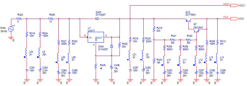
Here they exist two regulator circuits, that use the IC L200, as regulator of voltage and current, the company SGS-Thomson, which give these circuits. In circuit Fig.1, we can regulate the output voltage, with the RV1, while in the...
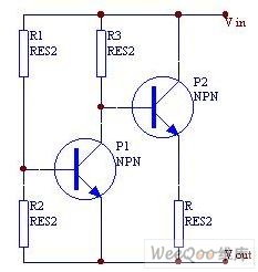
When the current is below the specified threshold, the bias current supplied by resistor R1 causes transistor P3 to saturate and conduct. In this state, it is unable to regulate the current effectively. Conversely, when the current reaches or...
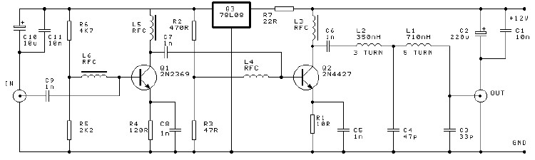
A high-efficiency, simple two-transistor VHF amplifier electronic circuit project can be developed using the provided circuit diagram. This VHF amplifier circuit achieves a significant efficiency with a gain of approximately 16 dB and does not require any tuning or...
The concept of distributed active RIAA correction and the use of negative feedback to linearize the input stage is appealing. However, the original design by Collin has significant flaws, including poor power supply rejection ratio (PSRR) in the input...
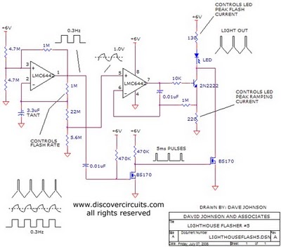
The aboriginal accessory forms a typical oscillator circuit that produces both a triangle waveform signal and a square wave signal. The triangle signal is fed into a voltage regulator circuit, which converts the triangle voltage signal to a triangle...
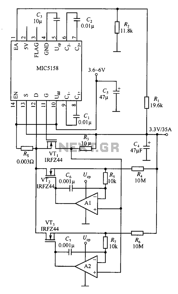
The MIC5158 is designed to manage tasks by controlling multiple external N-channel MOSFETs in parallel, which enables high current or high power output for a linear regulator circuit. This is illustrated in the accompanying figure. The operational amplifier circuit...