
Telephone status monitor
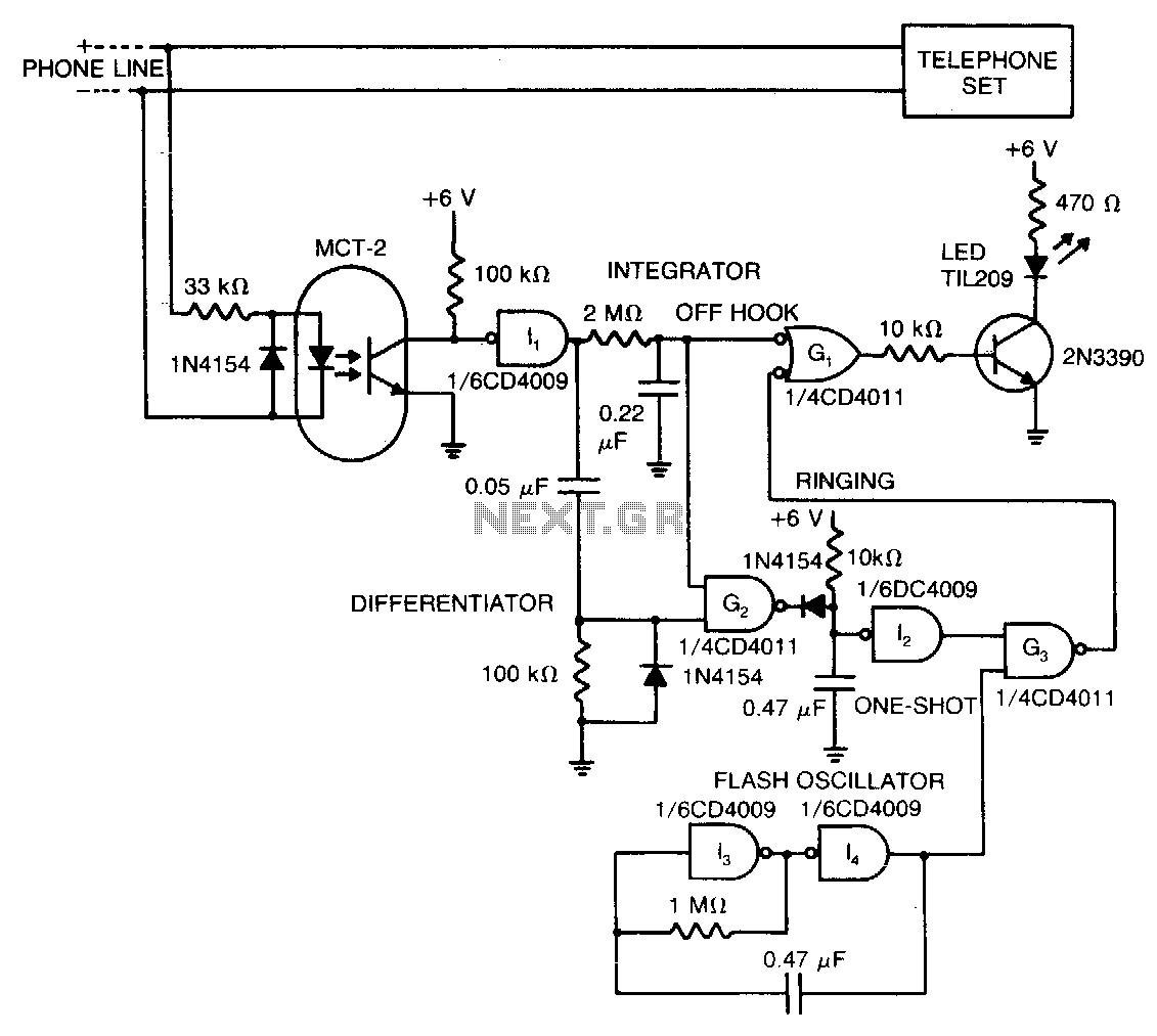
The described circuit utilizes an LED to visually communicate the status of a remote telephone line, incorporating a flashing oscillator and a NAND gate for control. When the telephone is not in use (hung up), the LED remains off, indicating an idle state. When the phone is off the hook, the LED illuminates steadily, signaling that the line is active. During incoming calls, the LED flashes in response to the ringing signal, providing an immediate visual alert.
The flashing oscillator, designed to operate continuously, serves as the heart of the circuit. Its output is contingent upon the presence of a ringing signal. When a ring signal is detected, it triggers a one-shot capacitor, which in turn enables NAND gate G3. This gate is responsible for controlling the LED's operation during the ringing state. The capacitor discharges quickly, allowing the NAND gate to toggle the LED on and off, creating a flashing effect. After the ringing stops, the LED continues to flash for an additional five seconds, ensuring that the user is aware of the missed call.
The circuit's design is efficient, as a single oscillator can manage multiple phone lines. This is achieved by connecting the oscillator output to multiple NAND gates, each corresponding to a different phone line. Each gate will activate the LED for its respective line based on the state of the one-shot capacitor, allowing for a compact and effective solution in multi-line telephone systems. This design is particularly useful in environments where monitoring multiple lines is necessary, such as in offices or call centers. Overall, the circuit provides a reliable method for indicating telephone status through a simple visual cue.The LED indicates the status of a remote telephone. The light is off if the phone is hung up. It shines steadily if the phone is off hook, and it flashes on and off while phone rings and for 5 seconds after ringing stops. The flashing oscillator operates continuously but can drive the LED only when a ringing signal discharges the one shot capacitor to enable NAND gate G3
Thus, one oscillator handles several phone lines. 🔗 External reference
Related Circuits
This thread explains the creation of a custom USB tire pressure monitoring system by modifying an aftermarket kit purchased on eBay. The initial step involved... The project entails the design and implementation of a USB tire pressure monitoring system (TPMS)...
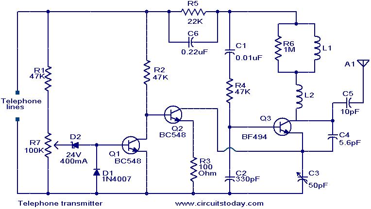
This circuit is a simple yet effective design for transmitting telephone conversations. When the telephone receiver is on-hook, the voltage across the lines is approximately 48 volts. The preset resistor R7 is adjusted to achieve a voltage of 24.7...
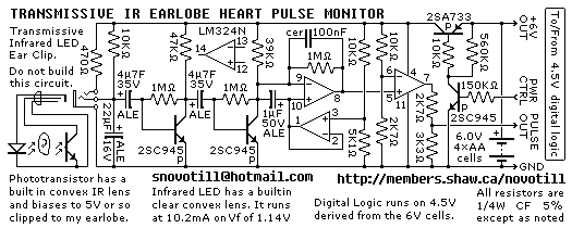
Senses heart pulse by means of an infrared earlobe clip. Reverse engineered circuit diagram of heart pulse sensor circuit board out of a treadmill. Notice that the output is level shifted for use by CMOS logic running on 4.5V...
Here is a design that you can own, tailor to your specific needs, layout on your circuit board and put on your bill of materials. Finally, you will be in control of the black magic (and high voltages) of...
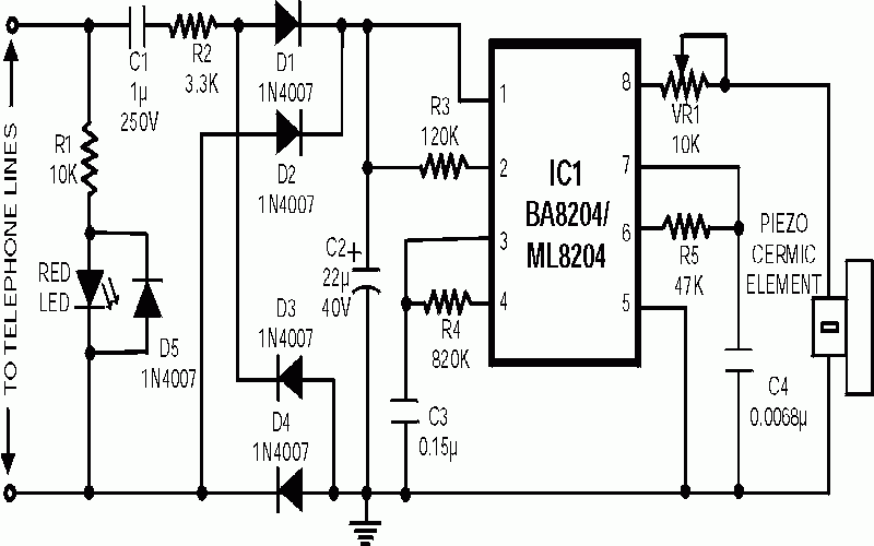
Many a times one needs an extra telephone ringer in an adjoining room to know if there is an incoming call. For example, if the telephone is installed in the drawing room you may need an extra ringer in...

When the voltage on the non-inverting input of each comparator exceeds the voltage at its inverting input, the output transitions to a high state, activating the corresponding LED. NOR gate latches are connected to the outputs of the third...