
Television Camera Experiments
In applications involving photodiodes, a high-impedance preamplifier is essential, even more so than with phototransistors. The JFET is the preferred amplifier type in this context. Although a JFET presents slightly more complexity than a bipolar transistor, it offers greater sensitivity than both bipolar transistors and vacuum tubes. Given that the output from the photodiode is a high-impedance signal, utilizing a JFET is advantageous. While the addition of a JFET introduces complexity, it can potentially reduce the number of required amplifier stages.
Coupling in this configuration employs high-impedance transistor preamplifiers, allowing for resistance-capacity coupling. This method of coupling was also favored by early television engineers. Resistance-coupled amplifiers tend to exhibit lower drift and greater stability compared to direct-coupled amplifiers. In contrast, conventional low-impedance transistor preamplifiers necessitate the use of electrolytic capacitors within the coupling network. New electrolytic capacitors often exhibit significant leakage, which increases over time, ultimately compromising the bias voltage of the transistor and leading to operational failure. Even prior to such degradation, these capacitors can distort television signals.
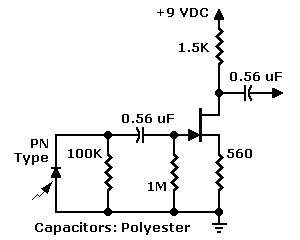
By utilizing a high-impedance preamplifier, the reliance on electrolytic capacitors can be minimized. Instead, it is advisable to use high-quality capacitors, such as mylar or polyester types. For bypass applications, the coupling and bypass capacitors have different requirements. In the referenced FET preamp, capacitor C1 serves as a bypass capacitor. A mylar or polyester capacitor of this value may not be readily available; however, a good-quality electrolytic capacitor is acceptable for C1, as it is not part of the signal path. Instead, C1 functions to filter out ripple and noise from the photodiode signal. For bypass and power supply filtering applications, electrolytic capacitors are generally sufficient, although larger paper or oil-filled capacitors can also be utilized. The challenge with electrolytic alternatives lies in sourcing them in a size and price that is reasonable.
This configuration emphasizes the importance of selecting appropriate components to ensure optimal performance of the high-impedance preamplifier while maintaining signal integrity and stability across the circuit.JFET input. PN photodiodes such as the popular "bullet cell" put out an extremely low-level signal. Yet photodiodes offer advantages over phototransistors. For example, more rapid response to motion. Also, some photodiodes have a peak response in the range of visible light. On the other hand, most phototransistors provide peak response in the infrared. For color reproduction, flat visible light response is essential. Anyway, with photodiodes, a high-impedance preamplifier is even more important than it is with phototransistors. For such applications, the JFET is the amplifier of choice. A JFET is only a little more difficult to work with than is a bipolar transistor. Yet a JFET is more sensitive than either a bipolar transistor or a vacuum tube. Since the output of the photodiode is a high-impedance signal, the JFET is a helpful idea. A JFET adds complexity, but will probably save you a few amplifier stages. Coupling. The high-Z (high-impedance) transistor preamp allows resistance coupling (actually "resistance-capacity" coupling).
In their amplifiers, the television pioneers used this same, resistance coupling. Because of their very limited drift, resistance-coupled amplifiers tend to be stabler than direct-coupled amplifiers. The low impedance inputs in normal transistor preamplifiers require electrolytic capacitors in the coupling network.
When new, these capacitors are dreadfully leaky. As the capacitors age, the leakage only increases until it destroys the bias voltage on the transistor. At that point, the transistor will block and quit operating. Even before the bias deteriorates, the capacitor can visibly alter television signals. Yet with a high-impedance preamplifier, you can avoid electrolytic capacitors. Instead, insist on premium capacitor, such as the mylar or polyester types. Bypass. Coupling and bypass capacitors don`t follow the same rules. In the FET preamp at left, notice bypass capacitor C1. You won`t find a mylar or polyester capacitor of this value. No worry. For C1, a good-quality electrolytic capacitor is fine. Unlike C2 and C3 in the same drawing, C1 isn`t in the signal chain. Instead, C1 is a bypass capacitor. C1 keeps ripple and noise out of the photodiode signal. For bypass and power supply filtering, electrolytic capacitors are adequate. Large-value, paper or oil-filled capacitors are fine, too. The problem with these electrolytic equivalents is finding one at a reasonable size and price. 🔗 External reference
Related Circuits
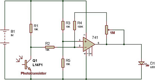
This versatile 741 operational amplifier module can be utilized to create a dark detector using a light-dependent resistor (LDR), a phototransistor, and a photodiode. The amplifier is configured in inverting mode, where it compares the voltage change at pin...
This model is very simple and charges as long as you hold the pushbutton: This circuit design features a straightforward pushbutton charging mechanism. The primary components include a power source, a pushbutton switch, a charging circuit, and a load. When...

The prototype circuit board utilized an external LCD display that received commands through an RS-232 interface. While this setup functioned adequately, programming it was cumbersome. Consequently, the circuit board was revised to support a directly attached LCD display. The...
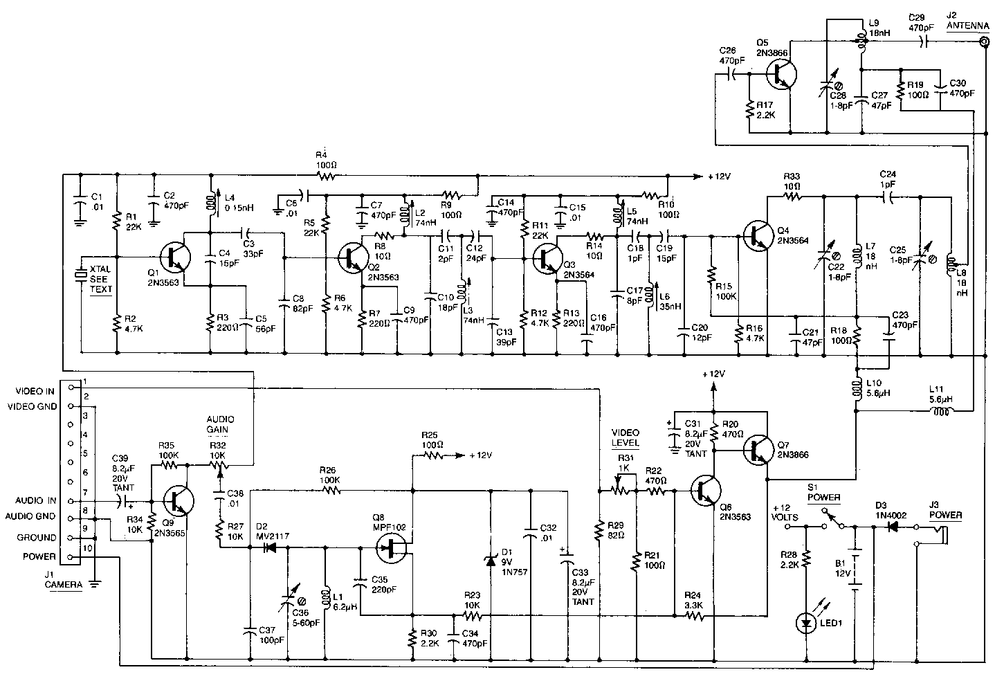
This high-performance video camera link transmits signals from a video camera to a VCR or from a VCR to TVs throughout a home. The initial stage of the RF chain features a crystal-controlled oscillator, Q1, operating at a frequency...

This circuit allows multiple cameras to be connected to a single monitor. It can be operated either manually or automatically. In automatic mode, a switch is connected to the output of a 555 astable multivibrator, which generates a continuous...
The Camera Head (A2075) is a LWDAQ device designed to control and read a single ICX424 image sensor. The circuit includes a socket for soldering a 16-pin sensor directly and features a 12-way flex socket for connecting an auxiliary...