
Camera Head (A2075) Manual
The Camera Head (A2075) operates as an integral component of a LWDAQ system, specifically designed for interfacing with the ICX424 image sensor series. The primary function of this device is to manage the readout and control of the sensor, which can be either monochrome (ICX424AL) or color mosaic (ICX424AQ). The circuit architecture is intentionally spacious, allowing for efficient heat dissipation and ease of access for soldering and connections.
The design features a dedicated socket for the 16-pin ICX424AL sensor, ensuring a reliable electrical connection. Additionally, a 12-way flex socket facilitates the connection of an auxiliary board, providing flexibility in sensor integration. It is crucial to note that only one sensor can be connected at any given time to prevent signal interference.
The ICX424AL sensor, located beneath a DSL821 lens, is notable for its automatic anti-blooming feature, which mitigates the saturation of pixels under high light exposure conditions. This capability is particularly beneficial in applications where dynamic lighting conditions are present. The sensor's pixel structure consists of 520 rows and 700 columns, with each pixel measuring 7.4 µm square, resulting in a total physical area of approximately 5.180 mm by 3.848 mm for the captured image.
For enhanced imaging capabilities, the A2075 supports pixel binning techniques. By combining four adjacent pixels into a single output pixel, the effective pixel size increases, resulting in a quadruple-sized pixel image. This method not only improves sensitivity but also maintains high contrast and brightness levels, even with reduced exposure times.
The device's architecture includes programmable logic to facilitate various operational modes, including single-pixel and quadruple-pixel readout configurations. The LWDAQ software further enhances the user experience by providing options for image display, analysis, and calibration. The calibration process allows for the adjustment of feature positions between single and quadruple pixel readouts, ensuring accurate measurements across different imaging scenarios.
In terms of compatibility, the A2075 is designed to work seamlessly with the LWDAQ drivers, specifically the A2071E and A2037E, which support both device types. The command bits for the A2075 conform to the LWDAQ specifications, enabling precise control over the sensor's functions, including read pulses and clock phases.
Overall, the Camera Head (A2075) represents a sophisticated solution for high-quality image acquisition, leveraging the capabilities of the ICX424 sensor series within a robust and adaptable circuit design.The Camera Head (A2075) is a LWDAQ Device that controls and reads out a single ICX424 image sensor. The circuit provides a socket into which we can solder the sixteen-pin sensor directly. It provides a twelve-way flex socket to which an auxiliary board holding the sensor can be connected. Connect only one sensor at a time. Figure: Camera Head (A20 75B) with Cover Removed. An ICX424AL monochrome image sensor is on the right side, beneath a DSL821 lens. The layout of the circuit is spacious, and provides both a footprint for an image sensor and a connector for an external image sensor. The square chip near the center is the programmable logic. For a photograph of an ICX424AL sensor see here. Below is an image we obtained with an ICX424AL monochrome image sensor and our A2075A prototype circuit board.
Figure: Fish-Eye View. This image taken with a DSL216A fish-eye lens, ICX424AL monochrome image sensor, and exposure time is 20 ms. The image is not intensified. It consists of 520 rows and 700 columns. In the example image, the over-head lights saturate the image pixels. Even if we divide the exposure time by a factor of a hundred, they still saturate the image pixels. And yet we see hardly any spread of this saturating charge into neighboring pixels. (The spread is called blooming, and the ICX424 provides automatic anti-blooming. ) When we block light to the sensor, the noise we see in the image is around 0. 2 counts, which is what we expect from quantization (1/ 12). With a 1-s exposure in the dark, we see no more than a few counts increase in the background intensity, which suggests we can expose with the ICX424 for many seconds at room temperature.
Figure: Fish-Eye View, Quadruple-Pixels. We combine blocks of four pixels with vertical and horizontal binning. The image consists of 260 rows and 350 columns. Each pixel corresponds to one 14. 8 m G— 14. 8 m pixels in the image sensor. Exposure time is 5 ms. We display the image without intensification. By combining rows and columns into pairs within the image sensor at the time we read out the image, we can create an image with pixels four times the size. The image above is such an image, but we display it with the same screen pixel size, so it appears to be one half the width and one half the height.
Notice that despite the fact that the exposure time is one quarter that of our full-size image, the contrast and brightness are roughly the same. This is because we are combining the charge from four pixels together into one output pixel. The ICX424AQ is a color mosaic image sensor we can read out with the same process as the monochrome sensor.
When we display the full-size image in our LWDAQ software, we use one of the LWDAQ color mosaic image intensification options, such as rggb. The color mosaic used by the ICX424AQ follows the same pattern used by the TC236P (see here ). The "rggb" in the name of the intensifiction tells the display routine to divide the image into four-pixel squares, in which the top-left pixel is red, and the bottom-left is blue, with the other two being green.
The ICX424AQ is approximately half as sensitive to light as the ICX424AL. This decreased sensitivity is a consequence of its color filters. Figure: Barrel Distortion. Lines are bent away from the center. The object is logarithmic graph paper 50 mm from a DSL821 lens, which is in turn 7 mm from the image plane. The DSL821 is a compound lens with an aperture. Whenever the aperture is separated from the lenses by a distance that is significant compared to the focal length, we expect to see either barrel or pin-cushion distortion.
The fact that we see barrel distortion suggest that the aperture towards the front of the compound arrangement. We do not expect such distortion in a BCAM, where our aperture is only 1 mm behind a lens of focal length 50 mm or 75 mm.
If we take a quadruple-pixel image with the ICX424AQ color mosaic sensor, we end up combining blocks of four pixels together into one. Each block of four pixels contains one red, two green, and one blue pixel. The combined result is a single, quadruple-size monochrome pixel with half the sensitivity of the quadruple-size ICX424AL monochrome sensor.
Thus we can use the quadruple-size readout with a color mosaic sensor, and obtain a monochrome image. But we cannot use the full-size readout with the color mosaic sensor to obtain a monochrome image, nor can we use the quadruple-size readout to obtain a color image.
The ICX424 is one of Sony Semiconductor`s Progressive Scan System CCDs. It comes in two packages, a 14-pin round ceramic DIP (see DIP14 ) and a 16-pin rectangular DIP (see DIP16 ). The sensor comes comes in a monochrome version and a color mosaic version. The ICX424AL is the 16-pin monochrome, and the ICX424ALB is the 14-pin monochrome. The ICX424AQ is the 16-pin color mosaic, and the ICX424AQB is the 14-pin monochrome. We built our first prototype with the 16-pin monochrome in the 16-pin package. The 16-pin package is 11. 6 mm G— 11. 4 mm, while the 14-pin package is a square 9. 5 mm on each side, with the corners rounded off on a 5-mm radius. The A2075A provides a footprint for the 16-pin package, but we can drive the 14-pin package through J2, the 12-way, 1-mm flex socket.
Resistor footprints R38 and R39 allow us to hard-wire one of the two possible sensors to the output amplifier of the A2075. If we connect an external sensor, we remove R39, which is a 0- © solder lump, and put a 0- © connection in place of R38.
The 14-pin package is significantly smaller, but Sony informs us that it is intended only for medical purposes, and is substantially more expensive than the 16-pin device. Thus we have no plans to use the 14-pin devices. The A2075D does not have a sensor on board, but instead connects to an auxilliary sensor head such as any version of the A2076.
The circuit is missing some parts called for on the page three of the schematic. The missing components are U11, C9, C10, C11, R39, and R38. A close relative of the A2075 is the BCAM Head ( A3025 ), which provides connection to two external image sensors and switches for six external light sources. On the screen of our computer, where our LWDAQ program displays the images we acquire from the ICX424, we plot the first pixel we obtain from the sensor on the top-left.
Subsequent pixels form the first row from left to right. Subsequent rows fill in the image from top to bottom. In our image analysis code, we use x for the horizontal image coordinate, and y for the vertical. Our origin is at the top-left corner of the top-left pixel. Thus x is left to right in the image and y is top to bottom. The following annotated photograph shows how x and y from the image display correspond to the layout of pixels on the image sensor itself. The first pixel we read out is the one on the top-left in the photograph, which is the one nearest to pin nine of the sixteen-pin package.
The ICX424 pixels are each 7. 4 m square. The image we obtain from the LWDAQ hardware has 700 columns and 520 rows. Thus the image corresponds to a physical area 5. 180 mm G— 3. 848 mm. We note that this ICX424 geometry is similar, but not identical to the geometry of our TC237B readout. The TC237B pixels were also 7. 4- m square. Figure: ICX424 Dark Pixels and Pin One Location. Both drawings from the ICX424 data sheet. The V and H arrows show the direction of movement of pixels during readout. The first pixel to be read out is the one next to pin 9. We identify pin 1 by looking for its unique pin shape, as seen on left end of package in the drawing.
As shown above, the ICX424 provides dark columns and rows around the image area. These dark pixels provide us with a border around the light-sensitive area, and give us pixels that we know are black. Our LWDAQ readout adds and subtracts some rows and columns, so that the actual dark border in a displayed image is slightly different from the border on the sensor itself.
The LWDAQ readout of the ICX424 provides 23 dark columns on the left and 17 on the right. There are twelve dark rows at the top and 12 on the bottom. When we need to specify the center of the image area, as we do for Rasnik Analysis and BCAM Analysis, we use the point that lies at the exact center of the image as it appears in the LWDAQ readout. The coordinates of this point, in microns from the top-left corner of the image, are x = 2. 590 mm and y = 1. 924 mm. When we read out the sensor with vertical and horizontal pixel binning, we end up with pixels that contain charge from four original image pixels.
These are quadruple pixels, and we need a new device type and dimensions, as shown below. You can set up the Camera Instrument with either of the above geometries by pressing its ICX424 or ICX424Q buttons (you will need LWDAQ 7. 7 or later). If we calibrate a camera with single-pixel readout, and subsequently operate the camera with quadruple-pixel readout, we can transform feature positions in the quadruple-pixel image into feature positions in the single-pixel image so as to apply the single-pixel calibration constants.
We add 44. 4 m to the x-coordinate and 7. 4 m to the y-coordinate we obtain from quadruple-pixel readout and so obtain the feature position in a single-pixel image captured from the same sensor. We measure the offset between quadruple and single pixel image positions here. The ICX424 comes in a color version also. The monochrome part is the ICX424AL and the color mosaic part is the ICX424AQ. The color mosaic places blue, green, and red filters over alternating pixels, and so allows us to deduce the color of the light incident upon the sensor.
To render the color image from such a sensor on the screen, we use the rggb types of image intensification. The A2075 is a LWDAQ device of type ICX424 (6) when we read it out one pixel at a time, and device type ICX424Q when we read it out with quadruple pixels.
The A2071E and A2037E LWDAQ Drivers support both device types, but you will need firmware version 2+ for the A2071E and 15+ for the A2037E. The A2075 command bits are assigned as follows. The assignment conforms to the LWDAQ Specification for device types ICX424 and ICX424Q, but does not include the bits that turn on and off light sources or select a second image sensor, because there are no light sources on the A2075, and we select the external image sensor with jumpers on the circuit board (R38 and R39).
The RDP bit, when combined with V2 and V3, causes a read pulse to be administered to the image sensor, transferring charge from the image area to the transfer columns. The H bit enables the horizontal clock phase in the circuit. The V1, V2, and V3 bits control the image sensor`s vertical clock phases. 🔗 External reference
Related Circuits
A compact and intriguing circuit designed to flash automotive headlights. The circuit diagram is based on the well-known NE555 timer circuit. This circuit utilizes the NE555 timer in astable mode to create a flashing effect for automotive headlights. The primary...
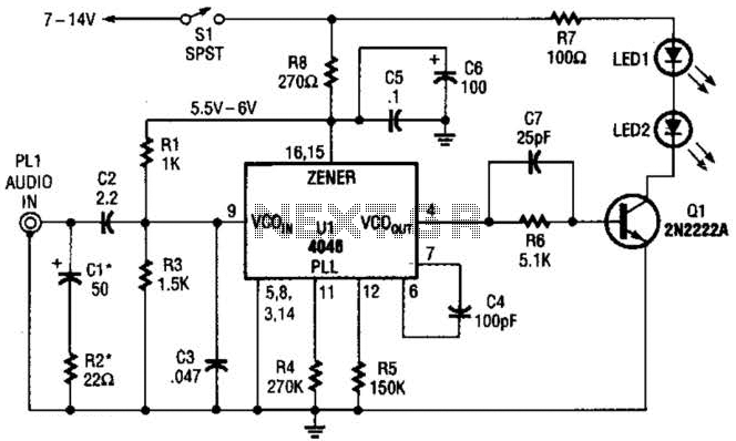
The transmitter for the wireless headphones is constructed using a CD4046 CMOS phase-locked loop, which is paired with a driver transistor and a set of infrared LEDs. While the CD4046 contains two phase comparators, a voltage-controlled oscillator (VCO), a...
This is an infrared (IR) remote control designed for Nikon cameras, specifically compatible with the Nikon ML-L3 remote control. The supported camera models include D40, D40X, D50, D60, D70, D70s, D80, Coolpix 8400, and 8800. The circuit design is...
This circuit must be connected to a 5 volt DC source. See my RR page for several 5 volt supplies. Note the flashing LED is optional, but looks so good on the top of a locomotive. The circuit described is...

This circuit allows multiple cameras to be connected to a single monitor. It can be operated either manually or automatically. In automatic mode, a switch is connected to the output of a 555 astable multivibrator, which generates a continuous...
The principle utilized in this electronic head or tail circuit is straightforward: a multivibrator controls a flip-flop. The multivibrator oscillates as long as the button S1 is pressed, while the flip-flop toggles on and off at a frequency of...