
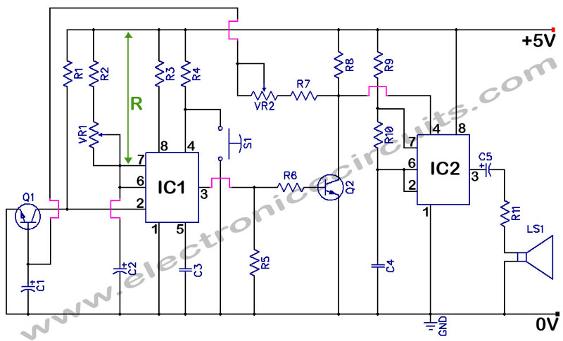
Temperature Alarm with Op-Amp Comparator

The comparator circuit functions by comparing two input voltages and producing a digital output that indicates which input is higher. In this configuration, the non-inverting input receives a fixed reference voltage determined by the resistor divider formed by R1 and R2. This reference voltage is crucial for setting the threshold at which the comparator toggles its output state.
The inverting input voltage is typically derived from a variable source, allowing the circuit to respond to changes in this input. The output of the comparator will switch states when the voltage at the inverting input exceeds the reference voltage at the non-inverting input. This characteristic makes the comparator useful in various applications, such as zero-crossing detectors, level shifters, and signal conditioning circuits.
To ensure stable operation, it is important to select appropriate resistor values for R1 and R2, considering the desired reference voltage and the input voltage range. Additionally, the circuit may benefit from hysteresis to prevent rapid switching in the presence of noise, which can be implemented by adding positive feedback through a resistor connected from the output back to the non-inverting input.
Overall, the comparator circuit is a fundamental building block in electronic design, enabling precise voltage comparisons and control in a wide array of applications.The circuit below is configured as a comparator. A fixed reference voltage at the non inverting input is provided by R1 and R2. The inverting input voltage is.. 🔗 External reference
Related Circuits
The main purpose of this design is to address a minor flaw in the widely used Fridge Door Alarm circuit, which has been available on this website since 1999 and has been constructed by many hobbyists. This circuit ceases...
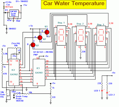
The Car Temperature Gauge is fundamentally similar to March's project, with some minor modifications to the input circuit. This circuit will display the water temperature with a resolution of 1 degree. The Car Temperature Gauge circuit is designed to accurately...
555 Timer with Audio Alarm Circuit. This circuit serves as a straightforward electronic timer equipped with an audio alarm feature. The 555 timer is a versatile integrated circuit widely used in various timer, delay, pulse generation, and oscillator applications. In...

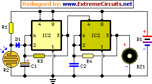
In a panic situation during the night when an intruder attempts to break into a house, this alarm system will assist by emitting a loud police siren to deter the intruder. The alarm system is designed to enhance home security...
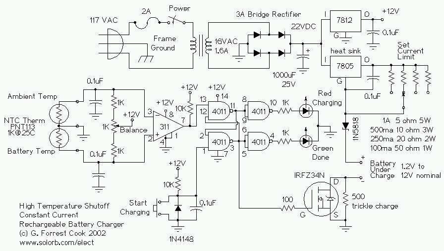
This circuit is designed for a temperature-controlled constant current battery charger, compatible with NiCd, NiMH, and other rechargeable cells. It operates on the principle that most rechargeable batteries exhibit an increase in temperature when they are fully charged. Overcharging...
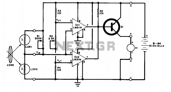
The change in ambient light triggers the alarm by changing the resistance of LDR1 and LDR2. The circuit utilizes two light-dependent resistors (LDR1 and LDR2) to detect variations in ambient light levels. LDRs are passive components that exhibit a change...