
Fridge Door Alarm Schematic 2nd Version
The circuit design focuses on enhancing the reliability of the Fridge Door Alarm by utilizing a more efficient configuration that operates effectively at lower voltage levels. The core components include two integrated circuits (IC1 and IC2), a photoresistor (R2), a capacitor (C1), a resistor (R1), a diode (D1), and a Piezo sounder. The integration of the photoresistor serves as a light sensor, which is crucial in determining the status of the refrigerator door.
When the refrigerator door is closed, the light sensor remains inactive, allowing the capacitor to charge and stabilize the circuit. The astable multivibrator configuration of IC1 ensures that once the light is detected, the circuit transitions from a stable state to an oscillating state, which is critical for triggering the alarm system. The output from IC1 is connected to IC2, which also operates as an astable multivibrator, generating the sound output through the Piezo sounder.
The design emphasizes energy efficiency, ensuring that the alarm system can function effectively even with a diminishing battery supply. By utilizing components that are more readily available and simplifying the circuit design, this approach aims to provide a practical solution for hobbyists and users looking for a reliable refrigerator door alarm system that can withstand lower voltage conditions.The main purpose of this design was to obviate a small defect of the very popular Fridge Door Alarm circuit, available on this website since 1999 and built by a lot of hobbyists. Unfortunately, that circuit stops operating when the battery voltage falls below about 2. 6 - 2. 7 Volts. This is due to the 4060 CMos IC used. In some cases, devices made by some manufacturers (but not Motorola`s) fail to operate even at nominal 3V supply voltage. A simple cure to this shortcoming could be the substitution of the original IC specified with a 74HC4060 chip: this should allow circuit operation down to 2V but, unfortunately, this IC is not easy to locate. For this reason, an equivalent circuit using about the same parts counting was developed, in order to allow safe operation even when battery voltage falls down to about 1.
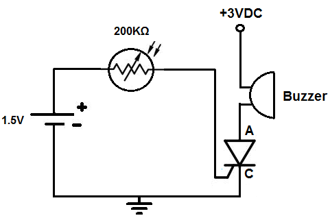
3V. The circuit, enclosed in a small box, should be placed in the fridge near the lamp (if any) or close to the opening. With the door closed, the interior of the fridge is in dark, the photo resistor R2 presents a high resistance (>200K) thus clamping IC1 by holding C1 fully charged across R1 and D1.
When a beam of light enters from the opening, or the fridge lamp lights, the photo resistor lowers its resistance (<2K) stopping C1 charging current. Therefore IC1, wired as an astable multivibrator, starts oscillating at a very low frequency and after a period of about 24 sec.
its output pin (#3) goes high, enabling IC2. This chip is also wired as an astable multivibrator, driving the Piezo sounder intermittently at about 5 times per second. The alarm is activated for about 17 sec. then stopped for the same time period and the cycle repeats until the fridge door closes. 🔗 External reference
Related Circuits

This is an enhanced version of the simple Garage/Shed Alarm. The entry and exit delays have been increased to approximately 30 seconds, and a timed siren cut-off and automatic reset have been added. The LED has been replaced with...

Analog baseband digital circuit table of contents: EMI interface, BPI bus, JTAG, LCD interface, keypad, UART, MINT, GPIO, MCP keypad, audio, RF, I/O connector, power cones, serial time, battery charging and analog, LED driver, RF control, JTAG, IOTA, audio...

This webpage outlines the radio transmitter unit that was part of the Cirrus One rocket mission in April 2001. The transmitter was included as a payload due to concerns about recovery challenges if the rocket drifted far downrange after...

When the sensor switch SW2 is pressed, the LED D3 and the alarm are activated for a certain duration. The timing of the circuit is determined by the resistor R3 and capacitor C1. Additional details regarding the RC circuit...
This circuit activates an alarm when tilted beyond a specific angle. Commonly used in various electronic devices, such as heaters, tip-over protection circuits can either shut off the device or trigger an alert. In this case, the circuit is...
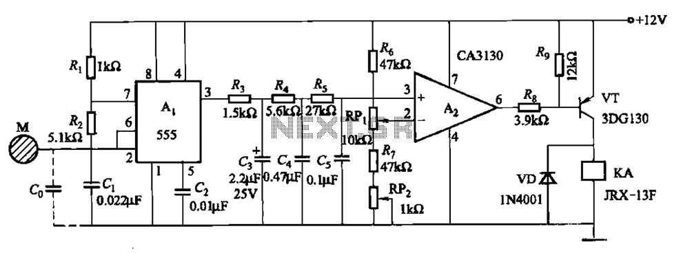
The circuit utilizes a 555 IC in conjunction with capacitors C1, C2, and a metal plate (tablet) M to create a distributed capacitance Co and resistor R1 connected to ground. Resistor R2 forms a self-excited multivibrator, while resistors R3...